2312
7
GB
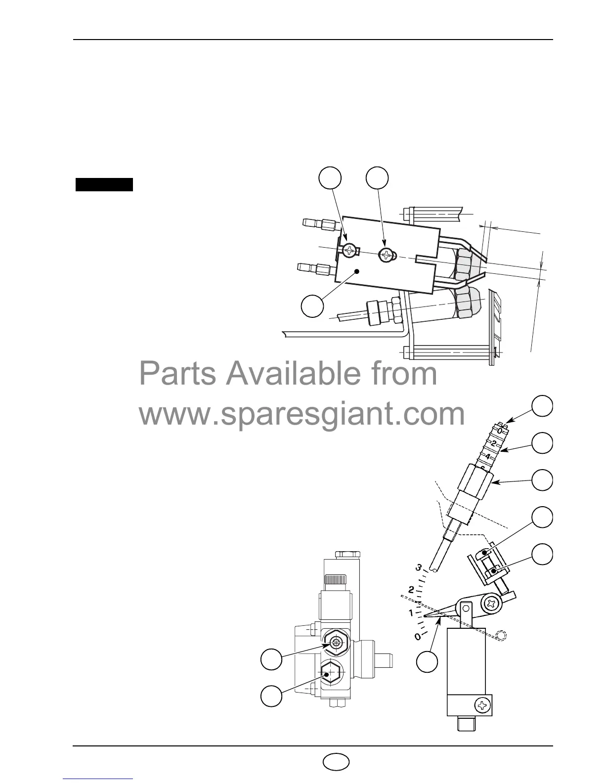
4.3 COMBUSTION HEAD SETTING (see fig. 12, page 6)
It depends on the output of the burner and is carried out by rotating clockwise or counterclockwise the setting
screw (6) until the set-point marked on the regulating rod (7) is level with the outside plane of the nozzles-
holder assembly (1).
➤ In the sketch the combustion head is set for an output of 2.00 + 2.00 GPH at 12 bar.
The set-point 3 of the regulating rod is at the same level with the outside plane of the nozzles-holder as-
sembly as shown in the schedule.
4.4 ELECTRODES ADJUSTMENT
1 1
MEASURES MUST BE RESPECTED.
For prospective adjustments loosen
screws (1) and move the electrodes as-
sembly (2), (see fig. 13).
WARNING
To have access to the electrodes carry
out operation as described in chapter
“4.2 RECOMMENDED NOZZLES”
(page 6).
Fig. 13
3
m
m
4
.
5
–
0
.
5
m
m
0
D5406
2
4.5 PUMP PRESSURE AND AIR OUTPUT
■
1
st
STAGE ADJUSTMENT
ADJUSTMENT OF AIR SHUTTER
Unloosen the nut (1), turn the screw (2) until the indicator (3)
reaches the position desired. Then lock the nut (1), (see fig. 14).
■
2
nd
STAGE ADJUSTMENT
ADJUSTMENT OF AIR SHUTTER
Unloosen the nut (4), turn the screw
(5) until the indicator (6) reaches the
position desired.
Then lock the nut (4), (see fig. 14).
PRESSURE REGULATION
This is set at 12 bar at the factory.
Should it be necessary to re-set or al-
ter such pressure, this can be done,
by adjusting screw (8).
The pressure gauge must be mount-
ed in place of cap (7), (see fig. 15).
When burner shuts down the air
damper automatically closes till a
max. chimney depressure of
0.5 mbar.
Fig. 15
D5407
5
6
4
2
1
3
Fig. 14
7
8
S7119