Do you have a question about the Riello RS 310/E FGR and is the answer not in the manual?
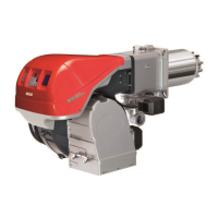
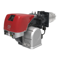
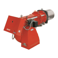
This document provides installation, use, and maintenance instructions for Riello forced draught gas burners, specifically the RS 310/E FGR, RS 410/E FGR, RS 510/E FGR, and RS 610/E FGR models, which operate in modulating mode.
These burners are designed for use with boilers operating with water, steam, diathermic oil, and other applications specified by the manufacturer. They are equipped with a Flue Gas Recirculation (FGR) system to reduce NOx emissions by reintroducing a proportion of flue gas into the combustion chamber, thereby lowering flame temperature. The amount of recirculated flue gas is controlled via auxiliary channel 3. The burners feature an air/fuel ratio control system that optimizes burner function in both individual installations and in combination with multiple heat generators. This system manages air and fuel dosage through direct servocommands, modulates burner output according to load requirements while maintaining boiler pressure or temperature, and supports cascade adjustment for multiple boilers.
The burners are available in various models with different power outputs and electrical specifications.
Power and Fuels:
Electrical Data:
Burner Weight (complete with packaging):
Control Box for Air/Fuel Ratio (BT330):
Operating Position: The burner is designed to operate in positions 1, 2, 3, and 4 (horizontal, vertical up, vertical down, and angled). Position 1 (horizontal) is preferred for maintenance access. Position 5 is prohibited for safety reasons.
Combustion Head Adjustment: The combustion head is adjusted by rotating a screw. The burner is factory-set at notch 0 for transport. Before start-up, adjustments must be made according to the required output and diagram. For RS 310 FGR models, central air/gas adjustment is factory-set at AIR = notch 9 and GAS = notch 0, and these settings should generally not be changed unless for specific cases.
FGR Duct System: The FGR duct typically connects to the stack with a 45° cut, centered in the stack. It should be routed to minimize elbows and allow for thermal expansion and contraction. Condensate drip legs are required upstream of the FGR control valve and shut-off valve to prevent condensation from flowing into the control valves and fan. The duct components must be sealed to prevent air leakage.
Gas Pressures: The manual provides tables and instructions for calculating and adjusting gas pressures at various points, including the combustion head and gas butterfly valve, based on the desired burner output and gas type (G20/G25).
Electrical Wiring: All electrical wiring must be performed by qualified personnel according to current regulations and wiring diagrams. The burner requires a disconnected electrical supply during installation and maintenance. FS1 burners are set for intermittent operation, requiring a stop at least once every 24 hours for safety checks.
User Interface (UI300): The UI300 display provides access to menu functions including INFO (burner details, fault history, software version, serial number, actuator positions, digital inputs/outputs), MANUAL (start/stop burner, adjust firing rate), SETTINGS (burner settings, actuator settings, air/fuel control system, curve sets, display settings), PASSWORD (access level changes), and DATASET PROCESSING (read/transfer datasets).
Firing-Rate Controller Module (LCM100): This module adds firing rate control functions, including an integrated power supply for external 24V consumers, LSB interface, 4-20 mA monitor output, digital pulse counter inputs for fuel consumption, and PT100/1000 input for flue gas temperature. It allows control of temperature or steam pressure and set-point shifts based on outside temperature.
Safety First: All maintenance, cleaning, and disassembly operations must be carried out with the electricity supply disconnected and the fuel interception tap turned off. Components in contact with heat sources must be allowed to cool down.
Maintenance Programme:
Safety Components Life Cycle: The manual specifies replacement intervals for safety components:
Faults and Solutions: The manual includes a list of fault codes (TRD and EN67) with descriptions and possible causes, along with D1 and D2 diagnostic codes. In case of a burner lockout, more than two consecutive reset operations can damage the installation. Interventions for lockouts or faults must only be made by qualified, authorized personnel.
| Brand | Riello |
|---|---|
| Model | RS 310/E FGR |
| Category | Indoor Fireplace |
| Language | English |