29
INSTALLATION
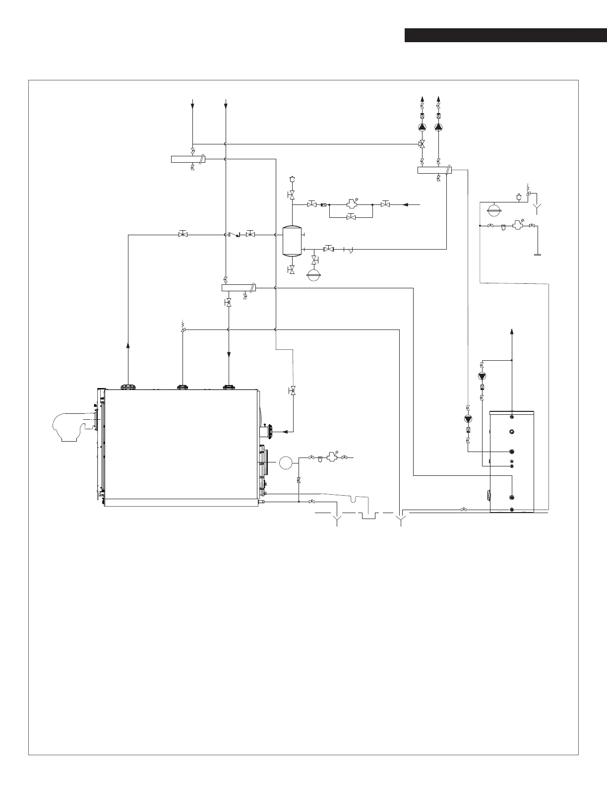
Single Boiler Combination Heating & Domestic Water Plant
3
3
24
3
4
5
3
3
4
5
3
21
3
12
10
3
20
226
15
6
3
3
3
11
3
3
3
3
4
3
23
3
5
3
24
16
16
16
1617
3
3
24
3
10
19
9
7
5
4
3
5
4
18
10
12
3
8
3
3
13
1
2
CENTRAL
HEATING
RETURN
LT RETURN (**)
FLOW
WATER
INLET
CENTRAL
HEATING
SUPPLY
MAKE-UP
WATER
INLET
DHW USER
POINTS
CENTRAL
HEATING
RETURN
HT
RETURN
25
1 Boiler
2 Burner
3 Isolation valves
4 Central heating system pump
5 Non-return valves
6 Automatic vent valve
7 Boiler safety valve
8 Boiler drain valve
9 Y strainer
10 Pressure reducer
11 Expansion tank
12 Water softener lter
13 Siphon
14 Condensate outlet
15 Drain
16 Isolation valve
17 Non-return valve
18 Air separator
19 Domestic water storage tank
20 Storage tank drain valve
21 DHW circuit expansion tank
22 Storage tank safety valve
23 3-way valve
24 Central heating system manifold
25 Pressure gauge
(*) LT= Low Temperature/HT= High Temperature
(**) On the RTC 1000-80 to RTC 4700-80 the low
temperature heating return is located on the top
of the boiler. See "Single Boiler Piping Schematic
Type A".