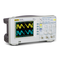
Do you have a question about the Rigol DS1052E and is the answer not in the manual?
Covers multiple safety instructions like proper power cord usage, grounding, and operation without covers.
Defines Measurement Category I and provides warnings regarding voltage limits and transient overvoltage.
Steps to inspect the shipping container, instrument, and accessories upon receiving the oscilloscope.
Guide to perform a quick functional check to verify the instrument is operating correctly.
Steps to adjust probe characteristics to match the oscilloscope channel input for accurate measurements.
Explanation of trigger controls, knobs, and status bar for setting up waveform triggering.
Configuration of channel coupling, bandwidth limit, probe attenuation, and digital filter settings.
Configuration of horizontal controls including time base, delayed scan, and display modes like Y-T, X-Y, Roll.
Detailed explanation of trigger modes, source, slope, sweep, and setup options for capturing signals.
Guide to using automatic measurements for voltage and time parameters, including displaying and clearing results.
Instructions for using Manual, Track, and Auto modes of cursor measurements for voltage and time analysis.
Solutions for common problems like a dark screen or waveforms not appearing after signal acquisition.
| Bandwidth | 50 MHz |
|---|---|
| Sample Rate | 1 GSa/s |
| Channels | 2 |
| Memory Depth | 1 Mpts |
| Vertical Sensitivity | 2 mV/div to 10 V/div |
| Input Impedance | 1 MΩ ± 2% || 15 pF ± 3 pF |
| Vertical Resolution | 8 bits |
| Trigger Modes | Edge, Pulse, Video, Slope, Alternate |
| Power Supply | 100-240 V AC, 45-440 Hz |
| Display | 5.7 inch TFT LCD |
| Interfaces | USB Host, USB Device, RS-232 |
| Dimensions | 303 mm x 154 mm x 133 mm |


