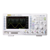
Do you have a question about the Rigol MSO8064 and is the answer not in the manual?
Safety precautions before instrument operation to avoid personal injury or damage.
Explains warning, caution, and danger terms used in the manual for hazard identification.
Defines DANGER, WARNING, CAUTION terms for product operations and potential hazards.
Illustrates and names product safety symbols like Hazardous Voltage, Safety Warning, Protective Earth Terminal.
Details measurement categories I, II, III, and IV for oscilloscope use based on transient voltage.
Specifies ventilation clearance and importance for oscilloscope operation and longevity to prevent overheating.
Details temperature, humidity, altitude, and installation overvoltage categories for safe instrument operation.
Defines pollution degrees 1 through 4 based on conductive and non-conductive pollution.
Classifies the product as a Class 1 - Grounded Product for electrical safety.
Provides instructions for proper care, cleaning, and avoiding damage to the instrument.
Addresses product compliance with WEEE Directive and recommendations for product end-of-life handling.
Lists the primary features and specifications of the MSO8000 series oscilloscopes.
Lists the chapters and their introductory content within the user manual.
Explains conventions for keys, menus, operation procedures, and connectors used throughout the manual.
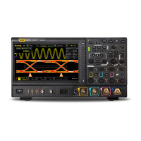
Details the MSO8000 series models and specifies MSO8104 as the example for illustrations.
Lists related product manuals and directs users to the RIGOL website for the latest versions.
Details the process of inspecting packaging, the instrument, and accessories upon receipt.
Provides front and vertical views of the oscilloscope with key dimensions in mm.
Guides on adjusting supporting legs and connecting to AC power, including grounding precautions.
Explains the procedure for starting the oscilloscope, self-tests, and welcome screen.
Provides step-by-step instructions for safely replacing the instrument's fuse.
Guides on connecting passive probes, including BNC terminal and ground connection.
Details how to perform function inspection, including restoring default settings and checking waveform.
Explains the procedure for compensating probes to ensure accurate measurements.
Provides a detailed description of the front panel components and their functions using a labeled diagram.
Details the rear panel interface components, including LAN, USB, and HDMI outputs.
Explains vertical controls like channel switch keys, offset, and scale knobs.
Details horizontal controls like zoom, search, navigation, position, and scale knobs.
Describes wave-related controls like Math, Logic Analyzer (LA), Reference Waveform (Ref), and Decode.
Explains trigger controls such as Menu, Mode, Force, and Trigger Level.
Describes the function of the Clear key to clear waveforms from the screen.
Explains the Auto key for automatic waveform setting and optimal display.
Explains the RUN/STOP key to control the oscilloscope's operating state.
Explains the Single key to set the trigger mode for a single acquisition.
Describes the non-menu and menu operations of the multifunction knob for adjustments.
Details the functions accessible via the Function Menu: Measure, Acquire, Storage, Cursor, Display, Utility.
Explains the function of the Touch Lock key to disable touch screen input.
Describes the Quick key for performing shortcut operations like screenshot and saving.
Explains the oscilloscope's user interface, including the LCD display and its elements.
Explains common methods for setting parameters using knobs, softkeys, and numeric keypad.
Instructions on how to use the security lock to fix the instrument's location.
Guides on accessing and using the oscilloscope's built-in help system for function keys and menus.
Explains how to view installed options and procedures for installing new ones.
Instructions on enabling and disabling analog channels (CH1-CH4) and activating them.
Details how to adjust the vertical scale of a channel using knobs, gestures, or the scale input field.
Explains how to expand or compress waveforms around the center or ground level.
Guides on adjusting the vertical offset of a channel using knobs, drag gestures, or the offset input field.
Explains how to set the coupling mode (DC, AC, GND) to filter unwanted signals.
Details the bandwidth limit function for reducing noise and attenuating high frequencies.
Explains how to set the probe attenuation ratio for accurate measurement results.
Describes the two input impedance modes (1 MΩ and 50 Ω) and their effects on measurements.
Explains how to enable or disable waveform inversion and its effect on measurements.
Discusses support for passive and active probes, including automatic recognition and ratio settings.
Explains how to select the amplitude display unit (W, A, V, U) for a channel.
Describes setting channel delay time to calibrate zero offset and correct for probe cable transmission delay.
Explains setting an offset calibration voltage to improve vertical parameter measurement accuracy.
Guides on setting custom labels for digital channels for easier identification.
Explains how to adjust the horizontal time base (scale) using knobs, gestures, or the scale input field.
Guides on adjusting the horizontal position (trigger point) using knobs, drag gestures, or the position input field.
Explains how to use the delayed sweep function to enlarge waveform details horizontally.
Describes the three available time base modes: YT, XY, and ROLL.
Explains the XY mode for voltage-voltage display and phase deviation measurement using Lissajous figures.
Describes the ROLL mode where waveforms scroll from right to left for updating the display.
Explains how to control waveform point generation using Normal, Average, Peak, and High Resolution modes.
Explains the real-time sampling mode and the maximum sample rates.
Details the process of sampling and the sample rates available in different channel modes.
Explains LA sampling and its sample rate, noting its relation to analog channel sample rate.
Defines memory depth and its role in storage capability, noting the standard depth of 500 Mpts.
Explains the anti-aliasing function to minimize aliasing possibility at slower sweep speeds.
Details horizontal expansion reference positions (Center, Left, Right, Trigger, User) for adjusting waveform display.
Explains how to select trigger sources from analog channels, digital channels, EXT, or AC Line.
Details how to adjust trigger level or threshold level based on trigger source type and displays real-time information.
Explains the trigger modes: Auto, Normal, and Single, and their operational characteristics.
Describes trigger coupling modes (DC, AC, LFR, HFR) for filtering components to the trigger path.
Explains trigger holdoff time to stably trigger on complex repetitive waveforms by waiting for re-arming.
Details the noise rejection function to reject high-frequency noise and reduce miss-triggers.
Lists the available hardware trigger types, excluding zone trigger.
Explains edge triggers based on trigger level/threshold level of the input signal's edge.
Details pulse triggers based on specified pulse width, defining positive and negative pulse width.
Explains slope triggers based on the positive or negative slope of the specified time.
Covers triggering on standard video signal fields or lines for NTSC, PAL, or SECAM standards.
Explains pattern triggers based on logical AND combinations of channel states and edges.
Details duration triggers that identify conditions based on the duration of a specified pattern.
Explains timeout triggers that activate when the time interval exceeds a preset value.
Describes runt triggers for pulses that pass one trigger level but fail another.
Covers window triggers that activate when the signal passes high or low trigger levels.
Explains delay triggers that activate when the time difference between specified edges meets a preset limit.
Details setup/hold triggers that activate when setup or hold time is less than a preset time.
Explains Nth edge triggers that activate after a specified idle time.
Covers RS232 triggers for start frame, error frame, or specified data of the RS232 signal.
Explains I2C triggers for start/stop conditions, missing acknowledgment, device address, or data values.
Details SPI triggers based on CS condition or timeout, and specified data.
Covers CAN triggers for start/end of frame, frame types, or error frames.
Explains FlexRay triggers for specified frame, symbol, error, or position.
Details LIN triggers for sync field, identifier, data, or frame.
Explains I2S triggers for specified data values, including clock, channel, and data sources.
Covers 1553B triggers for sync field, data word, command word, status word, or error type.
Explains zone triggers that use rectangle areas (Zone A, Zone B) to define trigger conditions.
Details the trigger output connector ([TRIG OUT]) for outputting trigger signals.
Explains how to perform various math operations (Arithmetic, FFT, Logic, Function) on waveforms.
Describes subtracting waveform voltage values point by point and displaying results.
Explains multiplying waveform voltage values point by point.
Details dividing waveform voltage values point by point for analyzing relationships.
Explains FFT operation for transforming time-domain signals to frequency-domain components.
Performs logic "AND" operation on waveform voltage values, defining logic levels.
Performs logic "OR" operation on waveform voltage values, defining logic levels.
Performs logic "XOR" operation on waveform voltage values, defining logic levels.
Explains logic "NOT" operation on waveform voltage values, defining logic levels.
Calculates the integral of the selected source, useful for measuring area or pulse energy.
Calculates the discrete time derivative of the selected source for measuring instantaneous slope.
Calculates the square root of the selected source point by point.
Calculates the base 10 exponential of the selected source.
Calculates the natural logarithm (Ln) of the selected source.
Calculates the exponential of the selected source.
Calculates the absolute value of the selected source.
Allows signals below a specified upper limit frequency to pass.
Allows signals above a specified lower limit frequency to pass.
Allows signals within a specified frequency range to pass.
Allows signals outside a specified frequency range to pass.
Applies a linear function (AX+B) to the selected source.
Averages waveforms of the specified channel multiple times for display.
Guides on setting labels for math operation results, using preset labels or manual input.
Provides auto measurements for 41 waveform parameters, statistics, and analysis.
Explains how to use the AUTO function for quick waveform setup and measurement.
Details how to set measurement parameters, sources, and enable/disable functions.
Defines and illustrates key time parameters like Period, Frequency, Rise Time, and Fall Time.
Explains how to count positive/negative pulses and rising/falling edges.
Covers delay and phase measurements between two sources, including formulas.
Defines various voltage parameters like Vmax, Vmin, Vpp, Vtop, Vbase, Vamp, Vupper, Vmid, Vlower, Vavg.
Details other parameters like Positive/Negative Slew Rate, Area, and Period Area.
Guides on selecting measurement categories (Horizontal, Vertical, Other) and setting measurement modes.
Explains how to select measurement sources for horizontal, vertical, and other parameter types.
Covers enabling or disabling measurement indicators.
Explains how to remove individual or all measurement items from the display.
Describes performing statistics on measurement results (Cur, Avg, Max, Min, Dev, Cnt).
Details how to perform and display all available measurements for the current source.
Explains cursor measurement for X and Y axis values, including manual, track, XY, and measure modes.
Guides on manually adjusting cursors to measure waveform values.
Explains selecting cursor types (X or Y) for horizontal or vertical measurements.
Details selecting the measurement source (channels, math, LA) for cursors.
Guides on adjusting the positions of X and Y cursors.
Explains selecting screen regions (Main, Zoom) for cursor measurement when delayed sweep is enabled.
Guides on setting horizontal and vertical measurement units (s, Hz, Degree, Percent).
Describes the track mode for measuring X and Y values on two different sources, with markers tracking waveforms.
Explains the XY mode for cursor measurement in XY time base mode, showing Lissajous figures.
Details selecting the Measure mode for cursor position display and enabling indicators.
Explains the built-in DVM for 3-digit voltage measurements on analog channels.
Guides on enabling or disabling DVM measurement and understanding its display.
Details selecting the measurement source from analog channels (CH1-CH4).
Explains selecting DVM modes: AC RMS, DC, and AC+DC RMS.
Guides on setting limits for beeper, condition settings, and upper/lower voltage limits.
Covers the frequency counter function for measuring frequency, period, or edge events.
Instructions on enabling or disabling the frequency counter measurement.
Details selecting the measurement source from analog/digital channels and EXT.
Lists supported measurement items: Frequency, Period, and Totalize.
Explains setting readout resolution for Period and Frequency measurements.
Describes clearing count results when Totalize is selected.
Guides on enabling or disabling statistical functions for Period and Frequency measurements.
Details parameters for power quality analysis of AC input lines.
Explains ripple analysis for evaluating DC power supply output ripple and measuring parameters.
Guides on enabling/disabling histogram analysis and its statistical view.
Explains the three histogram types: Horizontal, Vertical, and Measure.
Details selecting the source channels (CH1-CH4) for Horizontal and Vertical histograms.
Explains selecting measurement items when "Measure" histogram type is chosen.
Guides on setting the histogram bar graph height (number of grids).
Details setting the window range (Left/Right/Top/Bottom Limit) for Horizontal and Vertical histograms.
Explains enabling/disabling statistical display for histogram data.
Guides on resetting statistical data and restarting statistics.
Explains eye diagram as a statistical view of signal integrity, used for ISI and noise analysis.
Guides on enabling or disabling the eye diagram analysis function.
Details selecting the eye source from analog channels (CH1-CH4).
Guides on setting high, middle, and low thresholds for eye diagram analysis.
Explains clock recovery methods (constant, PLL, external) for comparing signal edges with ideal clock.
Guides on enabling/disabling display of eye measurement results like Eye Width, Height, Amp, Cross, Q Factor.
Explains how to reset the color level counter.
Covers jitter analysis for signal integrity and measuring measurement variance over time.
Guides on enabling/disabling jitter analysis and trend function.
Details selecting the jitter source from analog channels.
Refers to "To Set the Threshold" in Real-time Eye Analysis for jitter threshold settings.
Refers to "To Set Clock Recovery" in Real-time Eye Analysis for jitter clock recovery settings.
Explains setting jitter measurement items (TIE, Cycle to Cycle, Width) and graph display modes.
Guides on selecting digital channels (D0-D15) or user-defined groups.
Instructions on enabling/disabling individual channels or channel groups.
Explains setting threshold levels for D7-D0 and D15-D8 channels to distinguish logic levels.
Guides on setting waveform arrangement order (D0-D15 or D15-D0).
Details setting waveform display sizes (Small, Medium, Large).
Guides on setting custom labels for digital channels for easier identification.
Explains how to group or ungroup digital channels into user-defined groups.
Details setting colors for high logic level, low logic level, and edge display of digital waveforms.
Explains parallel bus decoding, including clock setting and bus setting parameters.
Details RS232 decoding, including baud rate, source setting, polarity, and data package settings.
Covers I2C decoding, including source and threshold settings, signal type, and display formats.
Explains SPI decoding, including mode, source setting, and data/display settings.
Details LIN decoding, including source, signal setting, baud rate, and display options.
Covers CAN decoding, including source, threshold, signal type, and baud rate settings.
Explains FlexRay decoding, including source, signal type, baud rate, and sample position settings.
Details I2S decoding, including source settings, WS settings, and bus settings.
Covers 1553B triggers for sync field, data word, command word, status word, or error type.
Guides on enabling the reference waveform function and selecting colors, sources, and display adjustments.
Details selecting the desired reference waveform channel (Ref1-Ref10).
Explains selecting the source channels (CH1-CH4, D0-D15, Math1-Math4) for reference waveforms.
Guides on adjusting vertical scale and offset of reference waveforms.
Instructions on saving displayed waveforms to internal memory as reference waveforms.
Explains how to clear the reference waveform display from the screen.
Guides on viewing detailed information about reference waveforms in a list format.
Explains how to restore the reference waveform to its original position.
Details setting colors for reference waveforms of different channels.
Guides on setting custom labels for reference waveforms using preset or manual input.
Instructions on saving reference waveforms to internal or external memory in various formats.
Guides on importing stored reference waveforms from memory to the instrument.
Guides on enabling or disabling the pass/fail test function, noting limitations.
Explains how to start, stop, test, and save mask ranges for the pass/fail test.
Details selecting the source channel (CH1-CH4) for the pass/fail test.
Guides on self-defining the pass/fail test mask by selecting region and adjusting tolerances.
Instructions on saving the current test mask range to memory in "*.pf" format.
Guides on loading test mask files from memory for the pass/fail test.
Details setting output events, aux output, polarity, pulse width, and error actions for test results.
Guides on enabling/disabling the display of test results statistics (failed, successful, total frames).
Explains how to reset current test results and execute statistics again.
Details common settings for waveform recording and playback, including record icon, process information, and play modes.
Guides on enabling waveform recording, setting parameters, and starting/stopping the recording process.
Explains how to start, stop, and control the playback of recorded waveforms.
Describes setting the current frame for waveform playback.
Guides on selecting recorded end or start frames for playback.
Details parameters for waveform recording, including interval, frames, and max frames.
Covers parameters for waveform playback, including play mode, sequence, interval, and start/end frames.
Details the search function for finding events based on trigger types like Edge, Pulse, Runt, Slope, etc.
Guides on copying trigger settings to search types or vice versa.
Explains enabling or disabling the display of the mark table.
Details setting event number for navigation and using navigation combination keys.
Instructions on saving event mark data to internal or external memory.
Covers navigation functions including recording/playing, time, and event navigation.
Guides on selecting waveform display modes: Vector or Dots.
Explains setting persistence time (Min, Specific Values, Infinite) for waveform display effects.
Guides on setting waveform intensity or brightness.
Details setting the grid type (FULL, HALF, NONE, IRE).
Guides on setting the grid intensity or brightness.
Explains enabling or disabling the scale display on the screen.
Details enabling or disabling color grade display for waveform acquisition probability.
Explains enabling or disabling the waveform freeze function.
Covers outputting basic waveforms like Sine, Square, Ramp, Pulse, DC, Noise, Sinc, Exp.Rise/Fall, ECG, Gauss, Lorentz, Haversine.
Details setting parameters for sine waveform: frequency, period, amplitude, high level, offset, low level, start phase, and impedance.
Explains setting parameters for square waveforms, including duty cycle.
Details setting parameters for ramp waveforms, focusing on symmetry.
Explains setting parameters for pulse waveforms, focusing on duty cycle.
Guides on setting offset and impedance for DC signals.
Details setting amplitude, offset, and impedance for noise signals.
Describes outputting Sinc waveforms and setting parameters.
Explains outputting Exp.Rise waveforms and setting parameters.
Details outputting Exp.Fall waveforms and setting parameters.
Explains outputting ECG waveforms and setting parameters.
Describes outputting Gauss waveforms and setting parameters.
Explains outputting Lorentz waveforms and setting parameters.
Details outputting Haversine waveforms and setting parameters.
Explains defining and saving arbitrary waveforms with up to 16,384 data points.
Guides on loading channel signals and setting waveform ranges using cursors or screen.
Covers creating arbitrary waveforms using frequency, amplitude, offset, and point editing.
Explains modulation types (AM, FM, FSK) using carrier and modulating waveforms.
Details Amplitude Modulation, including setting modulating waveform, frequency, and depth.
Explains Frequency Modulation, including selecting modulating waveform, modulation frequency, and frequency offset.
Details Frequency-shift Keying modulation, including polarity, frequency, and hopping frequency settings.
Covers sweep functions (Linear, Log, Step) for outputting signals from start to end frequency.
Covers burst waveform output with a specified number of cycles or infinite output.
Details the storage system, including USB HOST interfaces.
Describes storage file types: Image, Waveform, and Setup.
Guides on saving waveform settings and data to memory or external storage.
Explains saving oscilloscope setups to internal or external memory.
Describes the binary data format for storing waveform data with headers.
Details the information contained in the file and waveform headers.
Explains the two load types: waveform load and setup load.
Covers saving and loading image, waveform, setup, reference, and pass/fail test files to internal memory.
Guides on saving and loading files to/from external USB storage devices.
Details operations within the disk management interface: selecting file type, creating folders, deleting, copying, renaming, and clearing memory.
Explains how to input folder names using the English input method.
Describes inputting folder names using Chinese input methods.
Guides on deleting files or folders from internal and external memory.
Explains copying and pasting files or folders between internal and external memory.
Guides on renaming files or folders.
Instructions on clearing internal memory safely.
Explains how to restore the oscilloscope to factory default settings using the Default key.
Explains configuring remote communication interfaces: USB, LAN, and GPIB.
Guides on configuring LAN settings, including IP address, subnet mask, gateway, and DNS.
Details IP configuration types: DHCP, Auto IP, and Static IP.
Explains applying network parameter settings.
Mentions MAC address uniqueness for instrument identification.
Displays the VISA address currently used by the oscilloscope.
Provides user name and password for network configuration via LXI webpage.
Guides on enabling or disabling multicast Domain Name System (mDNS).
Explains how to input the host name for the oscilloscope.
Guides on setting the GPIB address for remote control via GPIB.
Details setting the status and resolution for the HDMI video output interface.
Explains PC communication via USB DEVICE interface, noting no configuration is required.
Covers system-related settings like beeper, language, and system information.
Guides on enabling or disabling the beeper for operations and prompt messages.
Explains setting the oscilloscope menu language (Chinese/English).
Guides on viewing oscilloscope system information (model, serial number, etc.).
Details setting system configuration to recall upon power-off.
Explains setting the power status (Switch On/Off) upon AC power connection.
Details setting the type of signal output from the [TRIG OUT] connector (TrigOut or Pass/Fail).
Explains outputting or receiving internal/external 10 MHz clock signals for synchronization.
Guides on accessing the built-in help system, viewing system info, options, and performing upgrades.
Explains performing self-calibration for optimal measurement results, considering ambient temperature.
Details setting parameters for the AUTO menu and quick measurement functions.
Guides on configuring network settings and printer parameters for printing the oscilloscope screen.
Explains setting up email transmission of files, including server login and attachments.
Guides on setting the front-panel keys to Locked or Unlocked.
Explains setting shortcut functions for the Quick key, including Image Saving and Waveform Saving.
Guides on saving the oscilloscope setup using the Quick key.
Details performing all measurements on the current source using the Quick key.
Explains resetting statistics for measurements or pass/fail tests.
Guides on printing the oscilloscope screen image using the Quick key.
Explains sending files via email using the Quick key.
Guides on recording waveforms using the Quick key.
Explains saving group settings for image, waveform, or setup.
Details enabling and configuring screen saver types and wait times.
Covers self-check functions including key test, screen test, and touch test.
Guides on setting the system time (year, month, date, hour, minute).
Details configuring default options, including impedance keep function.
Covers controlling the oscilloscope using SCPI commands.
Recommends RIGOL Ultra Sigma software for remote control via PC.
Explains using Web Control for real-time waveform display and remote control via web browser.
Guides on connecting the device and installing the USB driver for remote control.
Explains searching for the instrument resource using Ultra Sigma.
Details viewing the searched instrument resource under RIGOL Online Resource.
Guides on controlling the instrument remotely using SCPI Panel Control.
Details connecting the device, configuring network parameters, and searching for LAN resources.
Explains loading the LXI webpage via Ultra Sigma for instrument information.
Guides on connecting via GPIB, installing drivers, setting GPIB address, and searching for resources.
Lists checks for screen not turning on, including power connection and fuse.
Addresses issues with no waveform display, checking probes and signal generation.
Suggests adjusting horizontal time base or display type for ladder-like waveforms.
Provides troubleshooting steps for USB storage device recognition issues.
Addresses issues with touch screen functionality, including touch lock and screen cleanliness.
Lists available models, standard accessories, recommended accessories, and options with order numbers.
Outlines the product warranty terms and conditions provided by RIGOL.
| Brand | Rigol |
|---|---|
| Model | MSO8064 |
| Category | Test Equipment |
| Language | English |
