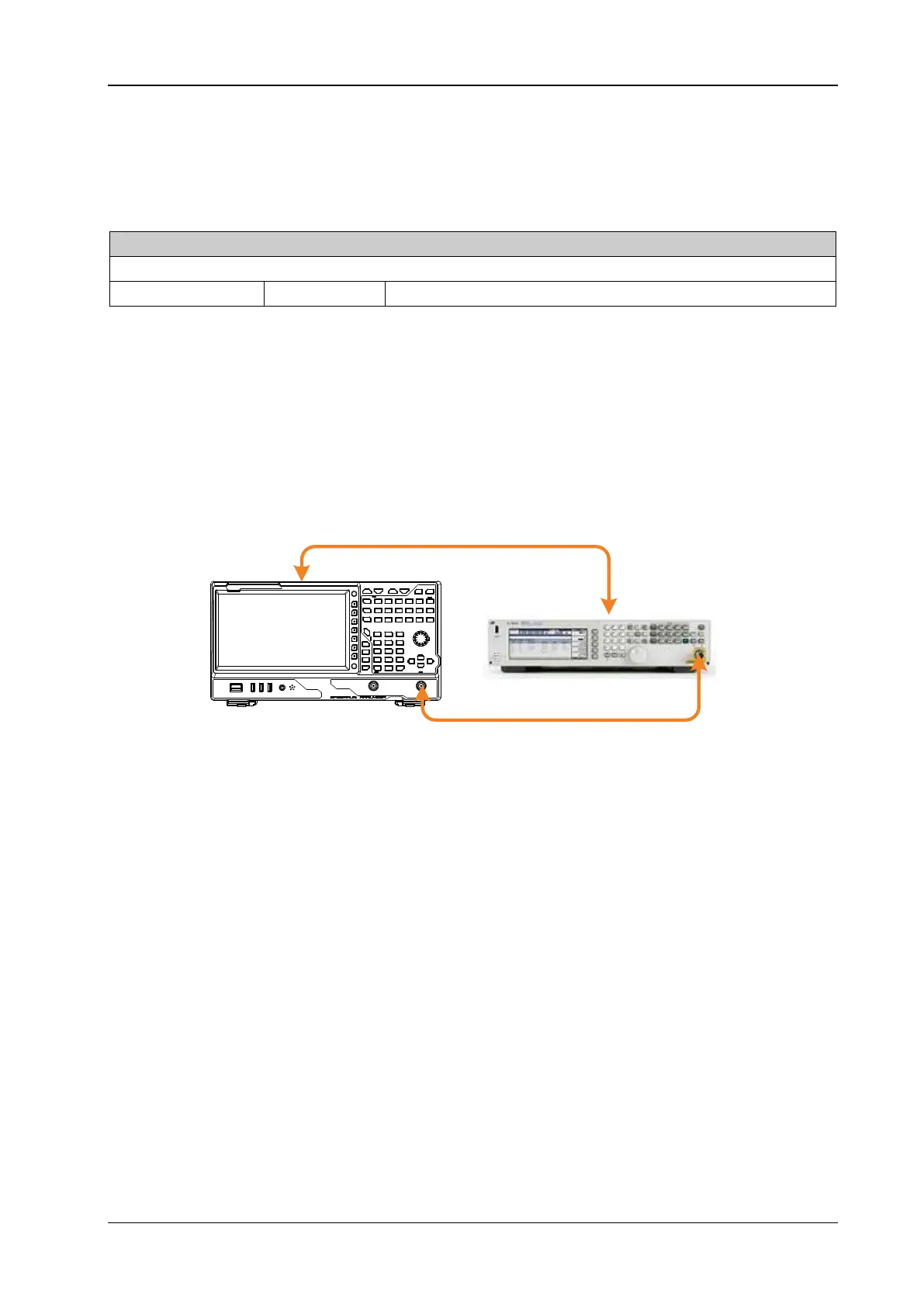
Figure 2-2 SSB Phase Noise Test Connection Diagram
Test Procedures
1. Synchronize the spectrum analyzer and signal generator.
2. Connect the output terminal of the signal generator with the RF input terminal of the spectrum
analyzer, as shown in Figure 2-2.
3. Set the signal generator to output a sine waveform with 500 MHz frequency and 0 dBm
amplitude.
4. Configure the spectrum analyzer (take 10 kHz offset as an example):
a) Set the center frequency to 500 MHz.
b) Set the span to 50 kHz.
c) Set the input attenuation to 10 dB; and set the reference level to 0 dBm.
d) Set the resolution bandwidth to 1 kHz, and set the video bandwidth to 30 Hz.
e) Set the trace type to Clear Write.
 Loading...