9 Rinnai Circ-Logic™ with Grundfos Kit
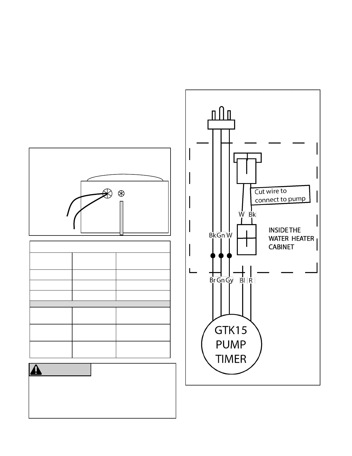
Figure 5: Electrical Diagram
Wiring Table
Description GTK15 (Timer) Supplied Line
Cord
+115VAC Brown (Br) Black (Bk)
Neutral Gray (Gy) White (W)
Ground Green (Gn) Green (Gn)
GTK15 (Pump) Rinnai
Circ-Logic™
+115VAC
(Circ-Logic™)
Red (R) Black (Bk)
Neutral
(Circ-Logic™)
Blue (Bl) White (W)
Figure 4: Bottom of water heater
CONDUIT
TO GTK15
POWER
CORDS FOR
WATER
HEATER AND
GTK15
CABLE ACCESS HOLES
FRONT OF WATER HEATER
9. Connect power to the water heater and the GTK15
line cord.
10. Set the mer switch to the actual me by turning
the programming ring in the direcon of the arrow
unl the ming arrow points to the actual me on
the ring.
11. Set the manual switch to “ON”.
12. Press the Power buon on the controller. The
pump and water heater will turn on to raise the
recirculaon loop temperature.
13. Refer to the Timer Operaon secon for addional
informaon on programming the mers.
The Grundfos GTK15 Pump has two power sources.
Disconnect all supply connecons before servicing.
One is directly from the electrical outlet for the mer
and the other is through the water heater for the
pump.
WARNING
RISK OF ELECTRIC SHOCK
 Loading...