REU-2532W Series 57 Rinnai
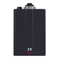
Transformer and
wiring harnesses.
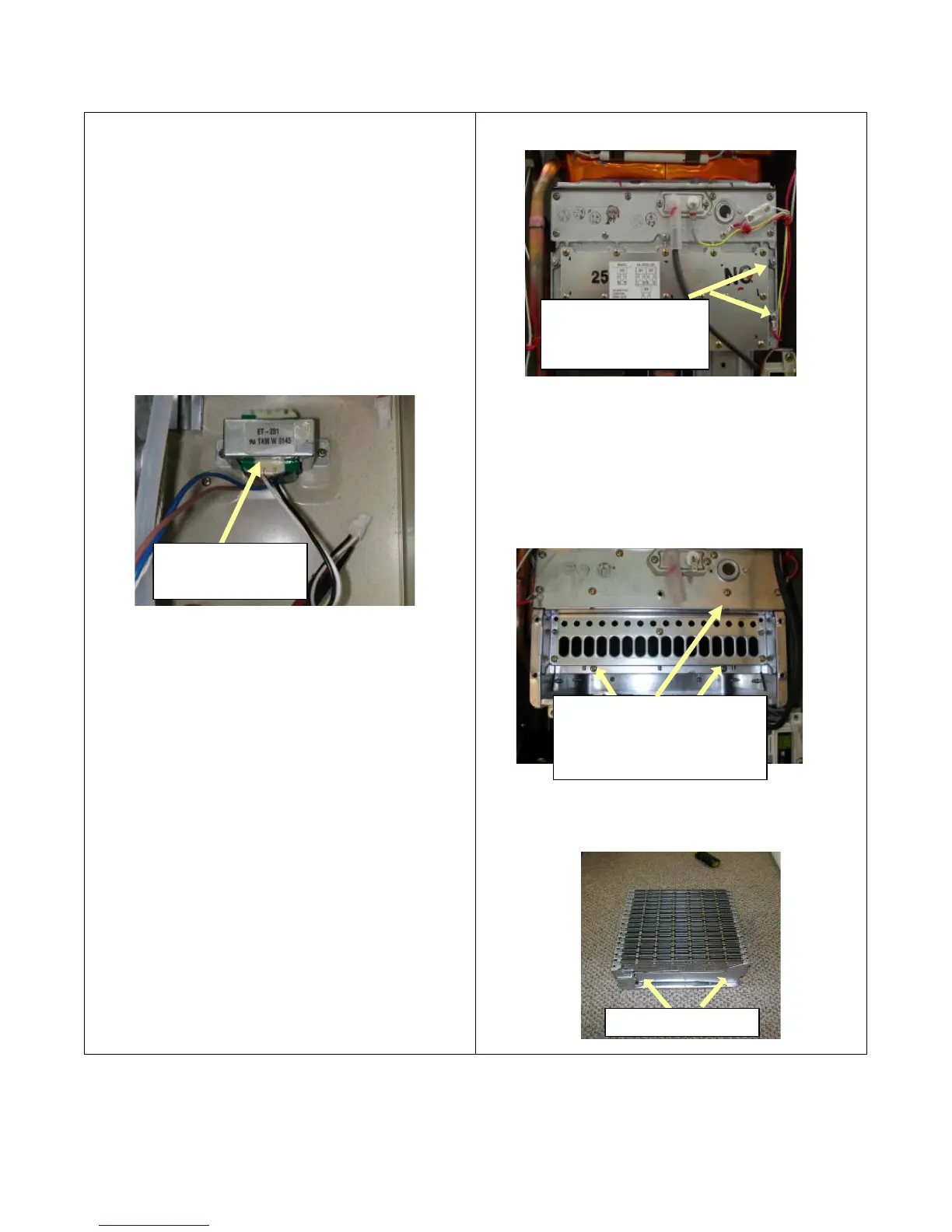
Burner assembl
.
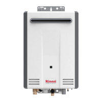
Remove (2) screws shown by
arrows and (8) screws in the
view glass panel above, then
pull burner out toward you.
Burner plate screws
(6), and (3) gas valve
assembly screws.
7. Removal of Transformer:
CAUTION
120 volt potential exposure. Isolate the appliance and
reconfirm power has been disconnected using a multi-
meter.
a. Remove the combustion fan motor assembly as
described in section 5-a,b.
b. Remove the two (2) Phillips screws to release the
transformer.
c. Disconnect wiring harness connectors to transformer
and pull out towards you.
8. Removal of Burner Manifold and the Burner:
CAUTION
120 volt potential exposure. Isolate the appliance and
reconfirm power has been disconnected using a multi-
meter.
a. To remove the burner manifold, remove (6) Phillip
screws around the burner plate as shown in the upper
right picture.
b. Remove the (3) Phillip screws at the gas valve
assembly.
c. Grip the burner manifold and remove it from the unit.
d. To remove the burner assembly remove (8) Phillip
screws around the sight glass panel. Remove this
panel.
e. Locate the (2) Phillip screws inside the burner
chamber that hold the burner assembly in place.
Remove these two screws, grip the burner assembly
and slide it out of the combustion housing.
f. If you need to remove each burner from this housing
remove the (2) Phillip screws on each side of the
burner, as shown below.
 Loading...