Rinnai 16 Commercial Manifold Pack OIM
REU-KM & REU-N MODELS ONLY
The HD, HDC, REU-KM & REU-N range of water heaters generate condensate continuously at a rate of up to 5
litres per hour as a by-product of highly ecient gas burner system. This condensate must be drained via a pipe to
a suitable point of discharge. Because the condensate is a by-product of gas combustion it is mildly acidic.
For this reason copper tube and ttings MUST NOT be used as it will corrode. Instead, Rinnai recommend plastic
pipes and ttings such as Unplasticised Polyvinyl Chloride (UPVC) or Polyethylene (PE) which is commonly used
for irrigation piping.
Important Considerations For Condensate Drain Pipe
The content of AS/NZS 3500 ‘Temperature / Pressure Relief and Expansion Control Valve Drain
Lines’ has been used as a guide in preparing these considerations.
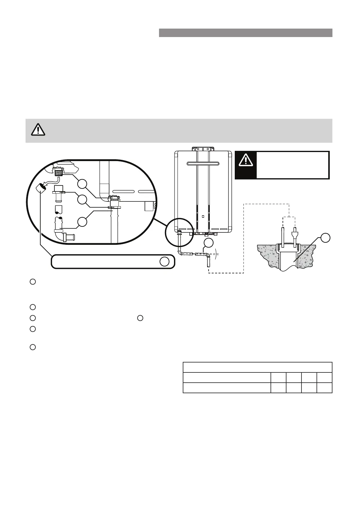
Water heater drain outlet connection, R½” (15 mm) BSP male. Condensate drain outlet connection, 1/2”
(15mm) BSP male nylon (Note: the black plastic shipping cap MUST BE removed from the condensate drain
outlet prior to water heater operation).
PE R½” BSP (15 mm) female to barbed irrigation system connector (13 – 19mm) or equivalent plastic tting.
Drain pipe and ttings to match item
B
.
Continuous fall (of at least 2°) from water heater to discharge point. Lengths and bends in accordance with
‘Length & Changes Of Direction’ table below.
Suitable points of discharge are deemed to be drains, sewers or pits. DO NOT discharge onto electrical
connections, earth stakes, copper pipes, concrete paths or into a pond.
Length & Changes Of Direction
Maximum length and changes of direction greater than
45° should be as follows:
Lengths and changes of direction
Max length (Metres) 9 8 7 6
Max changes of direction >45° 3 4 5 6
INSTALLATION METHOD
(a) The drain line MUST NOT discharge onto electrical connections, earth stakes, copper pipes, concrete paths
or into a pond.
(b) The point of discharge from each drain line shall be located so that the release of condensate does not cause
a nuisance, is readily discernible and incurs no risk of damage to the building.
In view of (a) and (b), suitable points of discharge are deemed to be drains, sewers or pits.
(c) There shall be no tap, valve or other restrictions in any line.
(d) Each line shall fall continuously from the valve to the approved point of discharge.
B
C
2°
D
B
A
C
E
A
Remove cap from condensate drain outlet
Condensate drain applies to
both internal and external
models, the external model
is shown in this illustration.
NOTE
CONDENSATE DRAIN