Rinnai 7 Commercial Manifold Pack OIM
CO-AXIAL FLUEING FOR INTERNAL MODELS
The Rinnai Continuous Flow Flueing system must be installed in accordance with the instructions supplied with
the ue terminal. Non Rinnai ueing systems MUST NOT be used. For all further information on Internal Flueing,
please refer to separate Flueing manual supplied with Flueing components.
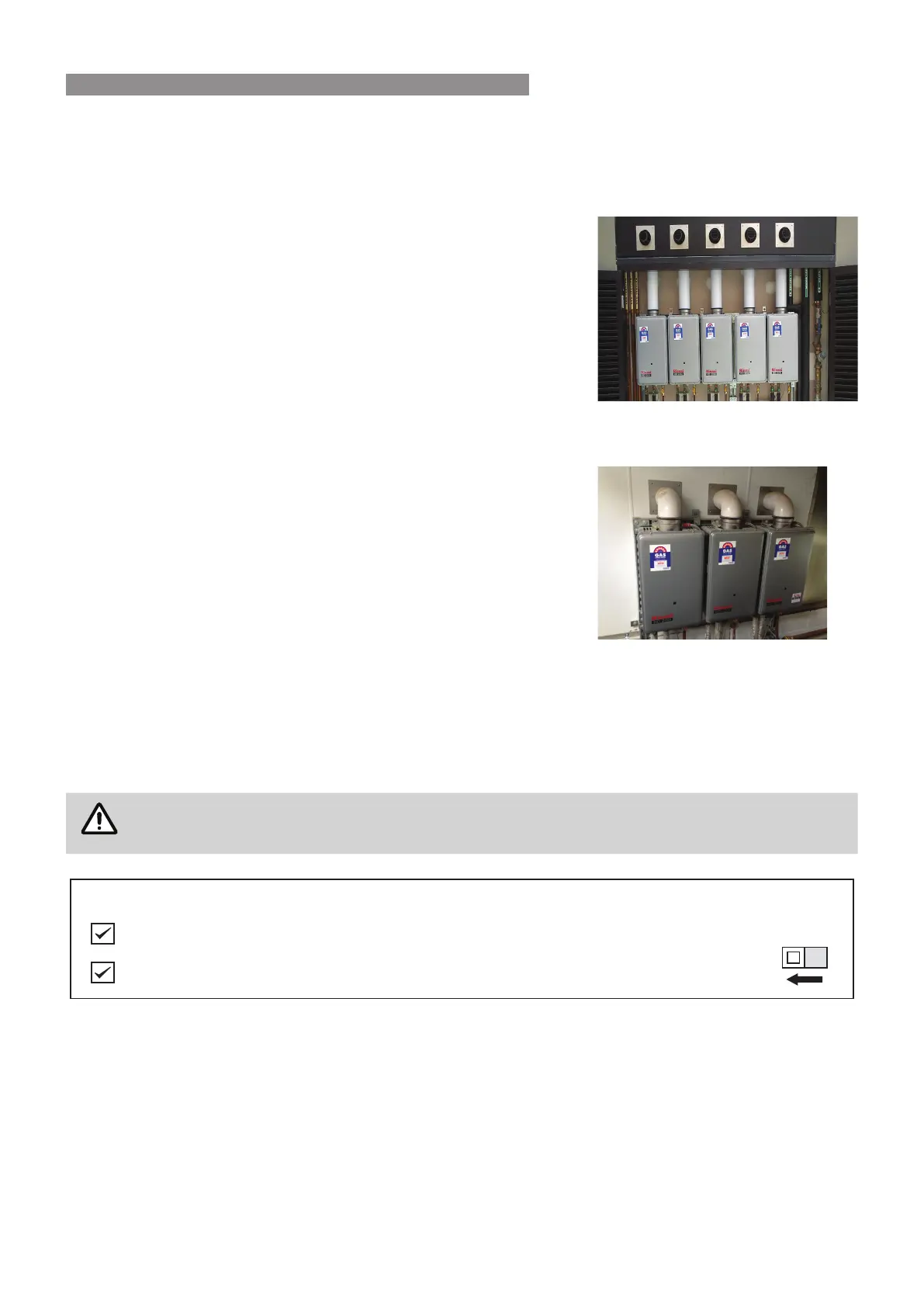
Installations can consist of both horizontal and vertical runs to a
maximum of 9 metres with a maximum of three 90° bends.
The Rinnai Internal Flueing system is highly versatile and makes
installation of an internal water heater simple and convenient. The ueing
for internal water heaters is a Co-axial design. It is manufactured from an
aluminium alloy inner ue pipe to discharge product of combustion and a
thermoplastic outer pipe for air supply to the appliance. The water heater
is a room sealed appliance.
Note: Each Rinnai water heater is ued individually.
As it is fan assisted, the heater can be ued vertically, horizontally or any
combination of both, to a maximum of 9 metres and 3 x 90 degree bends.
Horizontal ueing can be used as a direct wall ue or extended from
another internal wall.
Vertical ueing is used when the water heater needs to be ued vertically
through the roof.
A condensate trap is required when vertical ue exceeds 1.5 metres.
Rinnai HD internal water heaters are classied as 'room sealed'
appliances. Flue systems must be installed in accordance with Rinnai
Installation Instructions (supplied with the ue terminals), local gas
tting regulations, municipal building codes, AS/NZS 5601 and all other
relevant statutory regulations.
The ue terminal clearances AS/NZS 5601 DO NOT apply to the HD200e
and HD250e heaters installed side by side.
These appliance are AGA certied to be located side by side, for both
internal and external models.
Manifold Pack 5
Manifold Pack 3
Only Rinnai Flueing Systems can be used with Internal Water Heaters. Non-Rinnai Flueing systems
are not certied and will not be covered under warranty.
Have you used only RINNAI FFU flueing components?
1
OFF
SW1
For Internal (FFU) models only
If flue length exceeds 2m, dip-switch 1 of SW1 is to be switched to the ‘OFF’ position as shown.
For all further information on Internal Flueing, please refer to separate Flueing manual supplied with Flueing
components.
INTERNAL FLUEING
 Loading...