Rinnai 9 Commercial Manifold Pack OIM
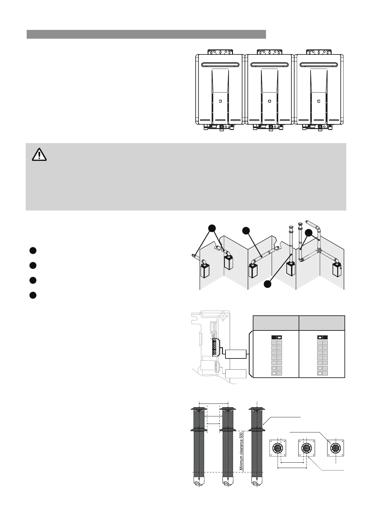
Multiple Appliance Installations
Dimension ‘h’ in reference to Horizontal Terminal
Clearances (Extract from AS/NZS 5601) on page 6
does not apply when multiple Rinnai external water
heaters of the same model are installed on the same
vertical face with ue terminals at the same height.
Under these conditions appliances can abut each other
as shown. The total gas consumption of all appliances
applies when determining other clearances.
For all other appliance dimensions, refer to "Appliance
Dimensions" on page 13.
Rinnai internal models described in this manual must use the Co-Axial Rinnai FFU ue components.
The use of non Rinnai FFU ue components may result in a dangerous situation and violates
regulations.
The FFU ue system must be installed in accordance with the ‘FFU Flue Installation Manual’
which is provided with the FFU ue terminal components FFWALLTERM or FFROOFCOWL.
Installations can consist of both horizontal and vertical runs to a maximum length of 9 metres
and with a maximum of three 90° bends.
Basic methods of installation
There are four basic ue installation methods available,
these are:
Direct Horizontal
Extended Horizontal
Vertical
Combination Vertical / Horizontal
Short and Long Flue Length Settings
Short Flue
When the ue length does not exceed 1.5m then: Dip
switch 1 of SW1 is to be switched to the 'ON' position.
Long Flue
When the ue length exceeds 1.5m the: Dip switch 1 of
SW1 is to be switched to the 'OFF' position (This increases
the combustion speed to overcome the additional friction
loses).
Multiple Terminal Installations
The terminal clearances stated in AS/NZS 5601 do not
apply to the Rinnai internal continuous ow water heaters
when they are installed side by side.
AGA certication allows for a horizontal separation of 160
mm for roof terminals and 270 mm for wall terminals.
1
2
3
4
OFF ON
SW1
1 2 3 4 5 6 7 8
FFU (Internal) Models Only
Short Flue: Total flue
length less than 1.5 metres
OFF ON
SW1
1 2 3 4 5 6 7 8
FFU (Internal) Models Only
Extended Flue: Total flue
length 1.5 metres or greater
Flue Length Dip Switch Settings
Dipswitches
SW1
Dipswitches
SW2
350
225
160
270
FFROOFCOWL
FFWPLATE
FFROOFCOWL
INTERNAL FLUEING