EasyManua.ls Logo

Rinnai REU-V1620WB User Manual

Rinnai REU-V1620WB
65 pages
To Next Page IconTo Next Page
Page #1 background imageLoading...
Page #1 background image
INFINITY 16 REU-V1616W
V1200 REU-V1620W
INFINITY 18 REU-V2018W
INFINITY 20 REU-V2020W
Rinnai High Capacity Continuous Flow Gas Hot Water System
NOTE: This manual does not apply to models: REU-V1620WG, REU-V1620WB, REU-V2024WG, REU-V2024WE,
REU-V2426WB, REU-V2626WG, REU-VM2630WD, REU-VM2630WC, REU-V2632FFUG, REU-VM2632FFUC
SERVICE MANUAL
Question and Answer IconNeed help?

Do you have a question about the Rinnai REU-V1620WB and is the answer not in the manual?

Rinnai REU-V1620WB Specifications

General IconGeneral
CategoryGas Heater
Heat ExchangerCopper
Ignition TypeElectronic Ignition
TypeTankless
Fuel TypeNatural Gas / Propane
Capacity16.0 GPM
Flow Rate16 L/min
Maximum Gas Rate (Propane)150, 000 BTU/hr
VentingDirect Vent
Warranty12 years on heat exchanger, 5 years on parts

Summary

Safety Warnings

Product Specifications

REU-V1616W/REU-V1620W Specifications

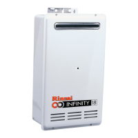
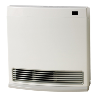
Details technical parameters for the Infinity 16 and V1200 models.

Sensors and Safety Devices

Water Flow Rates and Pressures

Unit Dimensions

Smartstart System

Smartstart Principle of Operation

Explains how the Smartstart system heats water in the pipework for efficiency.

Operational Flow Chart

Operation Principles

Ignition Process

Details the sequence of events from opening the tap to burner ignition.

Temperature and Flow Control

Explains how the PCB manages water temperature and flow rate.

Main Components Overview

Printed Circuit Board (PCB)

Controls all operational functions and interfaces with sensors and safety devices.

Remote Controls

Water Heater Installation Configurations

Wiring Diagram

Dip Switch Settings

Fault Finding Guide

Component Circuit Value Table

Component and Circuit Checks

Combustion Fan Circuit Checks

Procedures to test the combustion fan motor and its rotation sensor.

Sparker Circuit Checks

Steps to verify the sparker's voltage output and resistance.

Main Solenoid Valve (SV1) Circuit Checks

Guidance on checking the main solenoid valve's resistance and voltage.

Maintenance Monitor and Error History

Error History Display

Gas Conversion Procedure

Dismantling for Service

Related product manuals