Do you have a question about the Rinnai REU-V1620WG and is the answer not in the manual?
| Brand | Rinnai |
|---|---|
| Model | REU-V1620WG |
| Category | Gas Heater |
| Language | English |
Defines technical terms and symbols used throughout the manual for clarity and understanding.
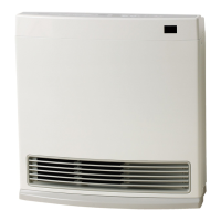
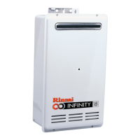
Provides an overview of the Rinnai V-Series hot water units and their key features.
Details the technical specifications, dimensions, and performance metrics of the hot water units.
Explains the function of various sensors and safety mechanisms integrated into the appliance.
Details water flow capabilities and pressure requirements for optimal operation.
Presents detailed physical dimensions and mounting information for different models.
Explains the operation and benefits of the Smartstart system for preheating water.
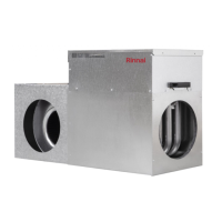
Provides visual representations of internal components for easy identification.
Maps out the sequence of operations and logic flow for the appliance's functions.
Explains the fundamental working principles of the hot water system's core functions.
Introduces and briefly describes the primary functional parts of the appliance.
Covers the functionality, types, and installation of optional remote controllers.
Illustrates operational sequences and timings for various combustion states.
Presents a schematic illustrating the electrical connections of all components within the appliance.
Explains how dip switches are configured to set operating parameters like gas type and temperature.
Provides a guide to diagnosing and rectifying common faults and error codes.
Lists electrical resistance and voltage values for various components to aid in testing.
Provides detailed procedures for testing the functionality of electrical components and circuits.
Explains how to access and interpret the appliance's operational history and error logs.
Lists and defines the various data points available through the appliance's display monitor.
Explains how to view the stored error codes and fault sequences.
Details the step-by-step process for converting the appliance between natural gas and LPG.
Provides a comprehensive guide to safely disassembling the appliance for maintenance or repair.
Provides detailed visual breakdowns of appliance parts for identification and assembly reference.
Lists all replaceable parts with their corresponding part numbers and quantities for each model.
A section for any miscellaneous notes or important reminders not covered elsewhere.