EasyManua.ls Logo

Rinnai REU-VM2630WD User Manual

Rinnai REU-VM2630WD
65 pages
To Next Page IconTo Next Page
Page #1 background imageLoading...
Page #1 background image
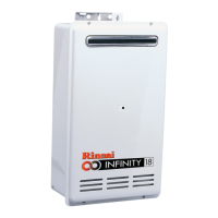
INFINITY 16 REU-V1616W
V1200 REU-V1620W
INFINITY 18 REU-V2018W
INFINITY 20 REU-V2020W
Rinnai High Capacity Continuous Flow Gas Hot Water System
NOTE: This manual does not apply to models: REU-V1620WG, REU-V1620WB, REU-V2024WG, REU-V2024WE,
REU-V2426WB, REU-V2626WG, REU-VM2630WD, REU-VM2630WC, REU-V2632FFUG, REU-VM2632FFUC
SERVICE MANUAL
Question and Answer IconNeed help?

Do you have a question about the Rinnai REU-VM2630WD and is the answer not in the manual?

Rinnai REU-VM2630WD Specifications

General IconGeneral
BrandRinnai
ModelREU-VM2630WD
CategoryGas Heater
LanguageEnglish

Summary

2. Specifications

7. Operational Flow Chart

8. Operation Principles

9. Main Components

11. Time Charts

12. Wiring Diagram

13. Dip Switch Settings

14. Fault Finding

Fault Finding Table

Lists faults, error codes, and corresponding actions for troubleshooting.

Component and Circuit Check Procedures

Details specific procedures for checking individual components and circuits.

Dismantling for Service

Provides instructions on how to safely dismantle the appliance for repair.

15. Component Circuit Value Table

16. Component and Circuit Checks

Combustion Fan Circuit

Checks for the combustion fan motor and its rotation sensor.

Sparker Circuit

Procedures for testing the sparker and ignition plug.

Main Solenoid Valve (SV₁) Circuit

Checks the main solenoid valve and its associated circuitry.

Solenoid Valve 1 (SV₂) Circuit

Checks the first solenoid valve (SV2) and its electrical connections.

Solenoid Valve 2 (SV₂) Circuit

Checks the second solenoid valve (SV2) and its electrical connections.

Modulating Valve Circuit

Procedures for testing the modulating valve's resistance and voltage.

Flame Rod Circuit

Checks the flame rod for proper function and electrical integrity.

Thermal Fuse Circuit

Procedures for checking the thermal fuse's resistance.

Overheat Switch Circuit

Checks the resistance of the overheat switch terminals.

Water Flow Sensor

Tests voltages related to the water flow sensor for proper operation.

Water Flow Servo Circuit

Checks voltages for the water flow servo and its connection.

Hot Water Outlet Thermistor Circuit

Checks the hot water outlet thermistor's resistance and temperature readings.

Anti-frost Heater Circuit

Measures resistance for the anti-frost heater components.

18. Maintenance Monitor / Error History

Error History

19. Gas Conversion Procedure

20. Dismantling for Service

REU-V1616W Parts List

REU-V1620W Parts List

REU-V2018W Parts List

REU-V2020W Parts List

National Help Lines

Related product manuals