Do you have a question about the Rinnai REU-VR2626W Series and is the answer not in the manual?
| Brand | Rinnai |
|---|---|
| Model | REU-VR2626W Series |
| Category | Water Heater |
| Language | English |
Guidance for resolving issues with wired and wireless water controllers.
Details compatibility between different water controller models.
Details possible faults and their corresponding error codes.
Summarizes electrical values for all components for diagnosis.
Detailed steps for checking individual components.
Procedures for checking the combustion fan motor and sensor.
Steps to check the igniter and its voltage and resistance.
Checks for the main solenoid valve, including voltage and resistance.
Tests for Solenoid Valve 1, including voltage and resistance checks.
Checks for Solenoid Valve 2 voltage and resistance.
Tests for Solenoid Valve 2 (Large), including voltage and resistance.
Checks for modulating solenoid valve voltage, resistance, and pressure changes.
Procedures to check the flame rod for current, voltage, and proper fitting.
Checks for thermal fuse resistance and potential PCB or fuse replacement.
Tests for the water flow sensor voltage and its connection.
Checks for water flow control device voltage and servo operation.
Checks thermistors for resistance at different temperatures.
Tests for surge protector fuses, supply voltage, and its components.
Tests resistance of anti-frost heater components and connections.
Checks resistance of the frost sensing switch at room and cool temperatures.
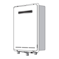
Procedure for removing the appliance's front panel.
Steps to remove the Printed Circuit Board unit.
Instructions for removing the water flow sensor and associated servos.
Procedure for removing the bypass servo component.
Steps for safely removing the appliance transformer.
Procedure for removing the sparker unit.
Instructions for removing the manifold and burner assembly.
Steps to disconnect and remove the gas control unit.
Procedure for removing the flame rod and spark plug.
Instructions for removing the outgoing water thermistor.
Steps to remove the heat exchanger thermistor.
Procedure for removing the anti-frost switch.
Steps to remove the anti-frost heater component.
Instructions for removing the appliance fan motor.
Detailed steps for removing the heat exchanger assembly.
Procedure for removing the thermal fuse from the heat exchanger.