Dip.SW1
3
14.
15.
16.
17.
18.
19.
20.
21.
1.
2.
3.
4.
Note: 'ON' towards front, 'OFF' towards rear.
5.
6.
7.
8.
9.
10.
11.
12.
13.
Turn 'OFF' the gas supply.
Turn 'OFF' power supply.
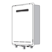
Remove the front cover from the
appliance.
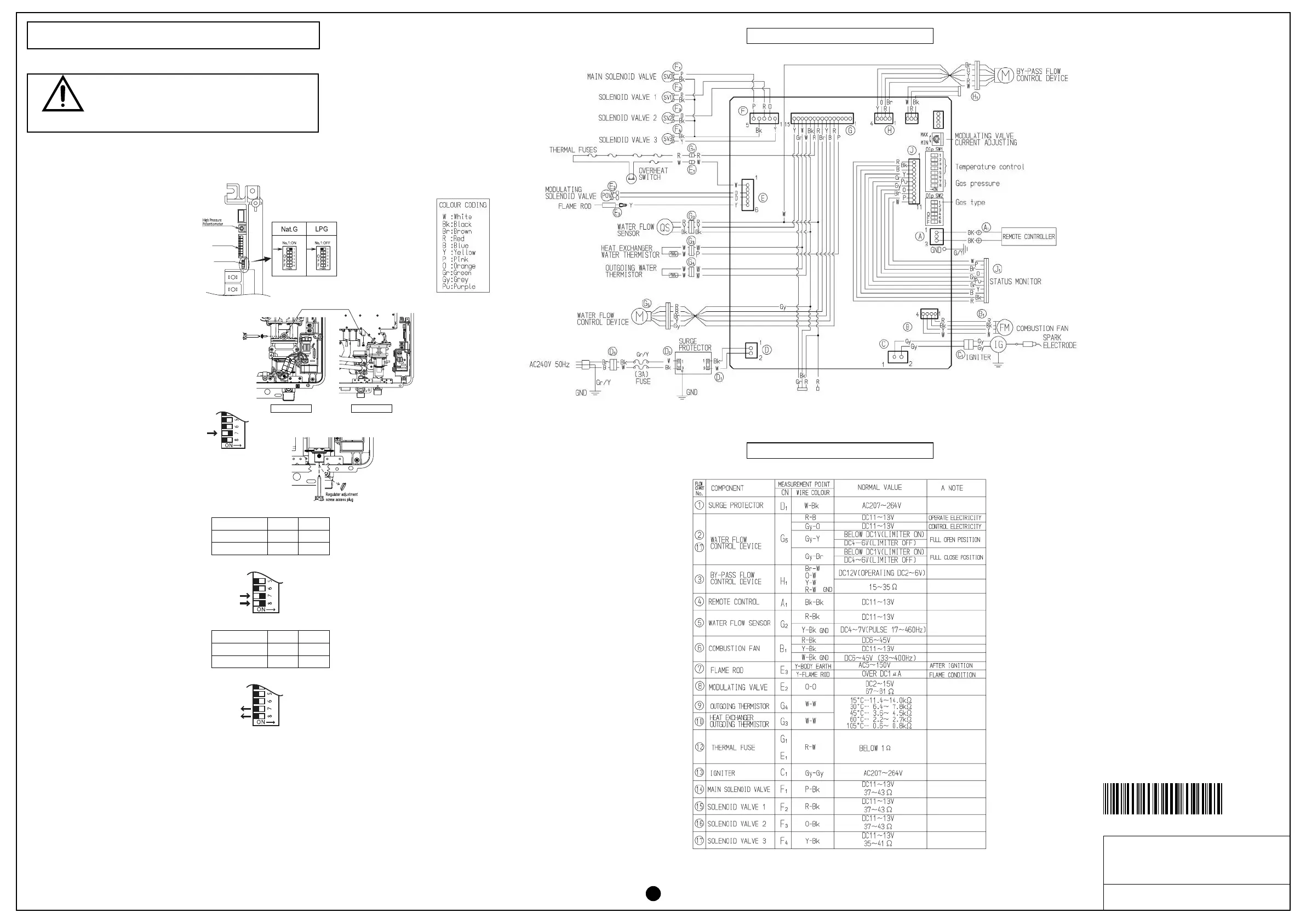
Check gas type switches (fig. 1) are in
the correct position (No.1 switch of
Dip.SW2 'ON' = NG, 'OFF' = LPG).
Attach pressure gauge to burner test
point, located on the gas control.
(fig. 2)
Turn 'ON' the gas supply.
Turn 'ON' power supply.
If remote controllers are fitted, turn the
unit 'ON' at the kitchen controller,
select the maximum delivery
temperature and open a hot water
tap fully. (CAUTION: Ensure
building occupants do not have access
to hot water outlets during this
procedure.)
Set the appliance to 'Forced Low'
combustion by setting No. 7 switch of
the Dip.SW1 set of dip switches to 'ON'.
(fig. 3)
Check the burner test point pressure.
Remove rubber access plug and
adjust the regulator screw on the
modulating valve (fig. 4) as required to
the pressure. (Table 1) Replace rubber
access plug.
Set the appliance to 'Forced High'
combustion by setting both No. 7 and
No. 8 switches of the bottom Dip.SW1
set to 'ON'. (fig. 5) Ensure maximum
water flow.
Check the burner test point pressure.
Adjust the high pressure Potentiometer
(POT) on the Printed Circuit Board
(PCB) as required to the pressure
shown Table 2.
IMPORTANT: Set No. 7 and 8 switches on the bottom (Dip.SW1) set
of switches to 'OFF' to return the appliance to 'Normal' combustion.
(fig. 6)
Close hot water tap.
Turn OFF the gas supply and power supply.
Remove pressure gauge, and replace sealing screw.
Turn 'ON' the gas supply and power supply.
Operate unit and check for gas leaks at test point.
Replace the front cover of the appliance.
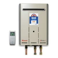
REU-VRM2632WC / VRM3237WC
GAS PRESSURE SETTING
DURING PRESSURE TESTING OF THE CONSUMER PIPING
ENSURE GAS COCK SITUATED BEFORE UNIT IS SHUT-OFF.
FAILURE TO DO SO MAY RESULT IN SERIOUS
DAMAGE TO THE APPLIANCE AND POSSIBLE INJURY.
WARNING
The regulator on the Infinity is electronically controlled and factory pre-set.
Under normal circumstances it does not require adjustment during
installation. Perform this procedure only if the unit is not operating correctly
and all other possible causes for incorrect operation have been eliminated.
fig.1
fig.2
fig.3
fig.4
fig.5
fig.6
VRM2632WC
Ta ble. 1 Pressure Setting LOW
0.14
0.18
VRM3237WC
Ta ble. 2 Pressure Setting HIGH
NG
0.23
0.23
LPG
VRM2632WC
0.73
0.80
VRM3237WC
NG
1.20
0.98
LPG
(kPa)
(kPa)
WIRING DIAGRAM
Dip.SW1(8P)
Dip.SW2(6P)
Dip.SW2
Dip.SW1
Dip.SW1
080 00012 31518 7
REU-VRM2632WC-ASN
REU-VRM3237WC-ASN
U298-902(00)
DIAGNOSTIC POINTS
Burner test point
VRM2632WC VRM3237WC
 Loading...