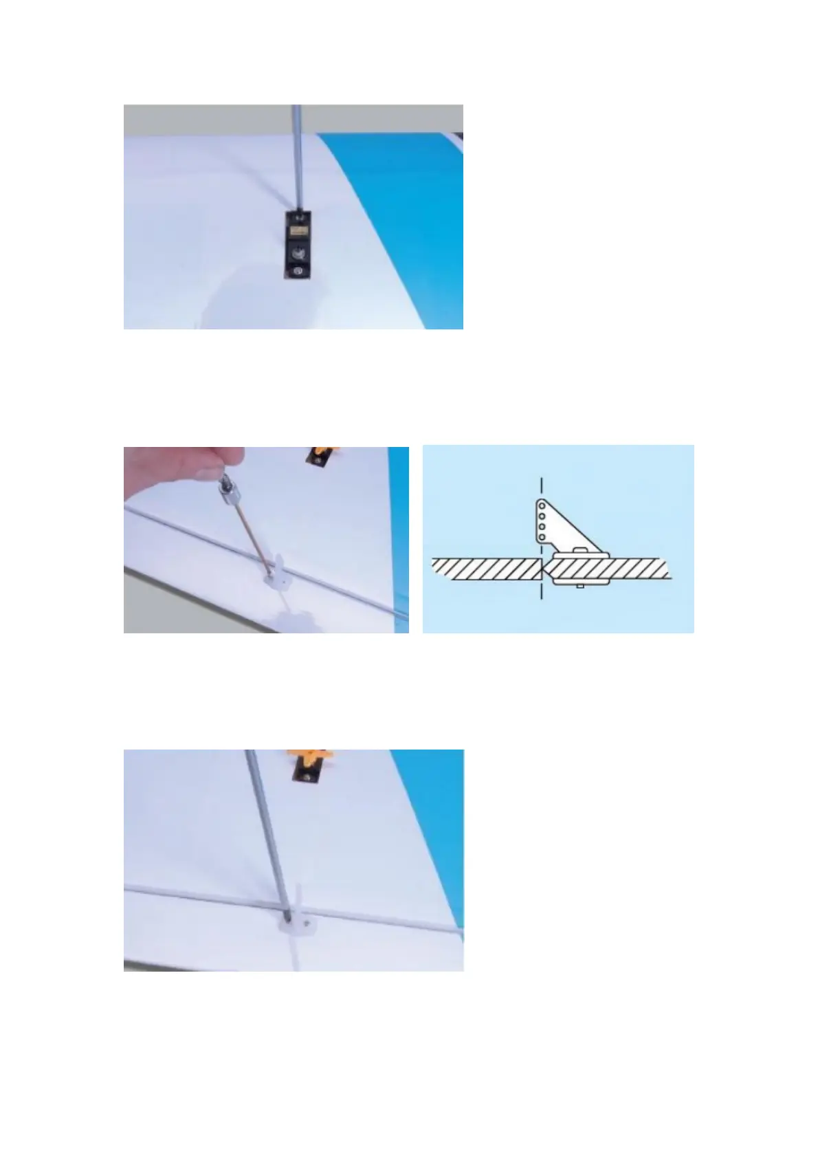
STEP 8
Locate the aileron control horns. They are screwed in position on the ailerons in line with the
aileron servo’s output arm. Align the row of holes in the horn with the hinge line. Mark and pilot
drill two mounting holes in each aileron.
STEP 9
Screw the aileron horns in position. The screws thread into the moulded horn plate on the top
surface of the wing. Do not overtighten the control horn mounting screws-you don;t wat to crush
the aileron.
 Loading...