GG
GG
TT
TT
44
44
88
88
00
00
II
II
nn
nn
ss
ss
tt
tt
aa
aa
ll
ll
ll
ll
aa
aa
tt
tt
ii
ii
oo
oo
nn
nn
MM
MM
aa
aa
nn
nn
uu
uu
aa
aa
ll
ll
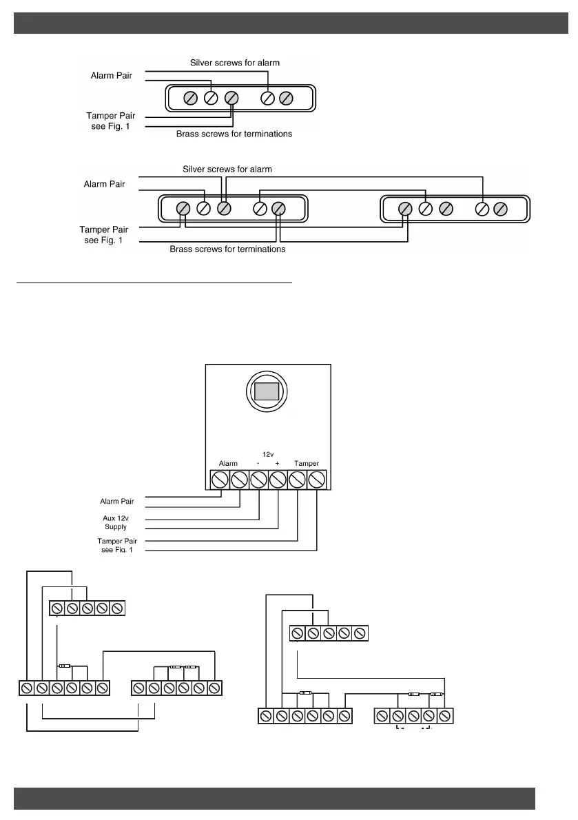
Fig. 2 Wiring Single Contact
Fig. 3 Wiring Double Contact (on the same zone)
Wiring Passive Infra-Red Detectors
It is essential when using Passive Infra-Red Detectors that you refer to the manufacturers
instruction as to the positioning and settings of the detector. This section is intended as a
guide to the wiring of the detectors.
Fig. 4 Wiring Single PIR
PP
PP
aa
aa
gg
gg
ee
ee
55
55
Note: Both detectors must be run on a single cable
from the Control Panel to the first detector
then the second. The 2K2 resistor must be in the
last/final detector.
Zone
12V
0V
D1 D 2
3K3
2K2
5K6
Alarm N/C Tamper N/C
1st Detector 2nd Detector
+ Power -
Alarm N/C Tamper N/C+ Power -
RKP
0V D1
Zone
12V D2
5K6
2K2
3K3
2nd Detector Door Contact
Alarm N/C Tamper N/C+ Power -
RKP
Alarm
Notes
Positions of terminals will vary
according to make.
All PIR wiring diagrams apply
also to Dual Technology
Detectors and Vibration sensors.
Fig. 5 Keypad Zones (480 RKP Only)
Note: Keypad zones (480
RKP Only) are preset
and cannot be changed.
E/E - 3K3 KP Zone 1
Access - 5K6 KP Zone 2
EOL - 2K2
GardTec 480 ENG PR5832 Rev 115IN480IM B A5booklet.qxd 18/07/2007 20:35 Page 5



 To Next Page