4
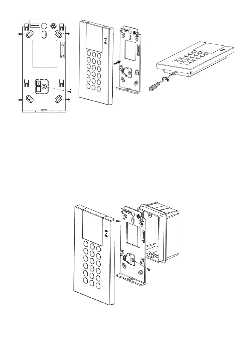
Figure 3
* Used for tamper
Figure 4 Figure 5
4. Connect the wires to the (AUX, COM and BUS) connector shown in Figure 7.
5. Mount the keypa
d to the mounting bracket (see Figure 4)
.
6. Insert the fast
ening screw to lock the keypad (see
Figure 5).
Moun
ting on Gang Box (Optional):
1. Repeat steps 1 to 2 in the previous procedure.
2. Secure the m
ounting bracket to the Gang Box using
the two screws as
ill
ustrated in Figure 6.
Figure 6
3. Mount the keypad to the mounting bracket and insert the fastening screw to
lock the
keypad














 To Next Page