5. Push Button
The push button should be wired to the “16 and “17” terminals. No matter the polarity. The gate operator
works alternately by pressing the button (open-stop-close-stop-open).
6. Exit Wand (optional)
The BLACK wire of the exit wand should be connected into the “14” terminal.
The BLUE wire of the exit wand should be connected into the “15” terminal.
The RED wire of the exit wand should be connected into the “18” terminal.
The GREEN wire of the exit wand should be connected into the “19” terminal.
The sensitivity adjustment board should be wired to the GREEN wire and the YELLOW wire of the wand. No
matter the polarity.
7. Battery
The “24V+” of the battery should be wired to the BAT+ (11) terminal, “24V-” should be wired to “-BAT” (10)
terminal. If the battery has been used with solar panel, please connect the batteries and the solar panel
&solar controller refers to the chapter “Connecting of the batteries & the solar panel & solar controller”.
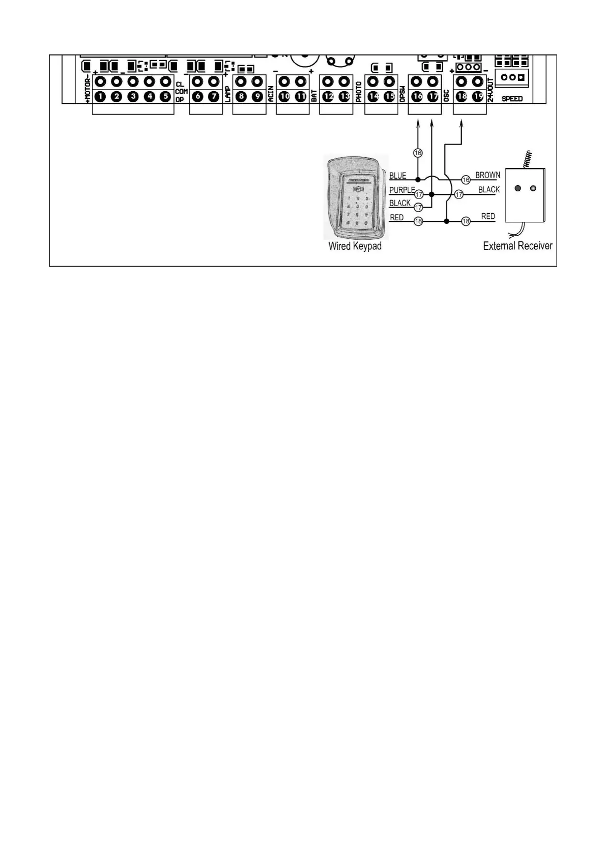
8. External Receiver
The BROWN wire of the external receiver should be connected into the “16” terminal.
The BLACK wire of the external receiver should be connected into the “17” terminal.
The RED wire of the external receiver should be connected into the “18” terminal.
9. Wired Keypad (24VDC)
The RED wire of the wired keypad should be connected into the “18” terminal.
The BLACK wire of the wired keypad should be connected into the “17” terminal.
The BLUE wire of the wired keypad should be connected into the “16” terminal.
The PURPLE wire of the wired keypad should be connected into the “17” terminal.
NOTE: Using of the photocell, exit wand, keypad and external receiver would cause the battery
exhausted quickly. Big capacity of batteries and big power of solar panel is required if you want to
use any one of them (If the batteries and solar panel is used as main power supply).
Setting Of the Control Board
WARNING: Ensure the gate opener is Power Off when you make any adjustment of the gate opener.
Keep away from the path of the gate during you set the gate opener system in case of the
unexpected gate moving. Carefully adjust the DIP switches to avoid the risk of machine damage and