5 Installation
EN
22 Rittal roof-mounted Blue e+ cooling unit/VX25 Blue e+ integration solution
Please be sure to observe the applicable regulations
governing electrical installations of the country in
which the device is installed and operated, as well as
national regulations for accident prevention. Please
also observe any internal company regulations, such
as work, operating and safety regulations.
The technical specifications and limit values stated
must not be exceeded under any circumstances. In
particular, this applies to the specified ambient tem-
perature range and IP protection category.
5.2 Siting location requirements
When choosing the installation location, observe the fol-
lowing notes:
– The installation location, and hence the arrangement
of the cooling unit, must be chosen to ensure good
ventilation (the separation between cooling units and
the clearance to the wall must be at least 200 mm in
each case, and 500 mm from the louvred grille).
– The cooling unit must be installed and operated in a
horizontal position (maximum deviation: 2°).
– The installation site must be free from excessive dirt,
aggressive ambient conditions and moisture.
– The ambient temperature must be within the limits
specified on the rating plate.
– It must be possible to fit a condensate water discharge
(see section 5.3.4 "Connect the condensate water
discharge").
– The mains connection data as stated on the rating
plate of the cooling unit must be guaranteed.
Size of installation room
– Units SK 3185730 and SK 3185730 must not be in-
stalled in rooms of less than 3 m³.
Electromagnetic interference (EMI)
– Interfering electrical installations (high frequency) must
be avoided.
– Signal cables must be laid separately from live cables.
5.3 Assembly procedure
5.3.1 Assembly instructions
Before mounting the roof-mounted cooling unit, en-
sure that the enclosure is sealed on all sides (IP 54). In-
creased condensate water occurs if the enclosure is
not airtight when it is put into operation later.
If necessary, also mount on the enclosure, on which
the roof-mounted cooling unit is to be mounted, a
door limit switch (e.g. 4127.010) that switches off the
cooling unit when the enclosure door opens and so
prevents an increased condensate water accumula-
tion (see section 3.1.7 "Door limit switch"). This is al-
ready standard for the integration solution.
Please ensure that the electronic assemblies in the en-
closure allow the even circulation of air.
Under no circumstances should the air inlet and outlet
openings of the cooling unit be obstructed. Only in this
way is it possible to ensure that the maximum cooling
output is available.
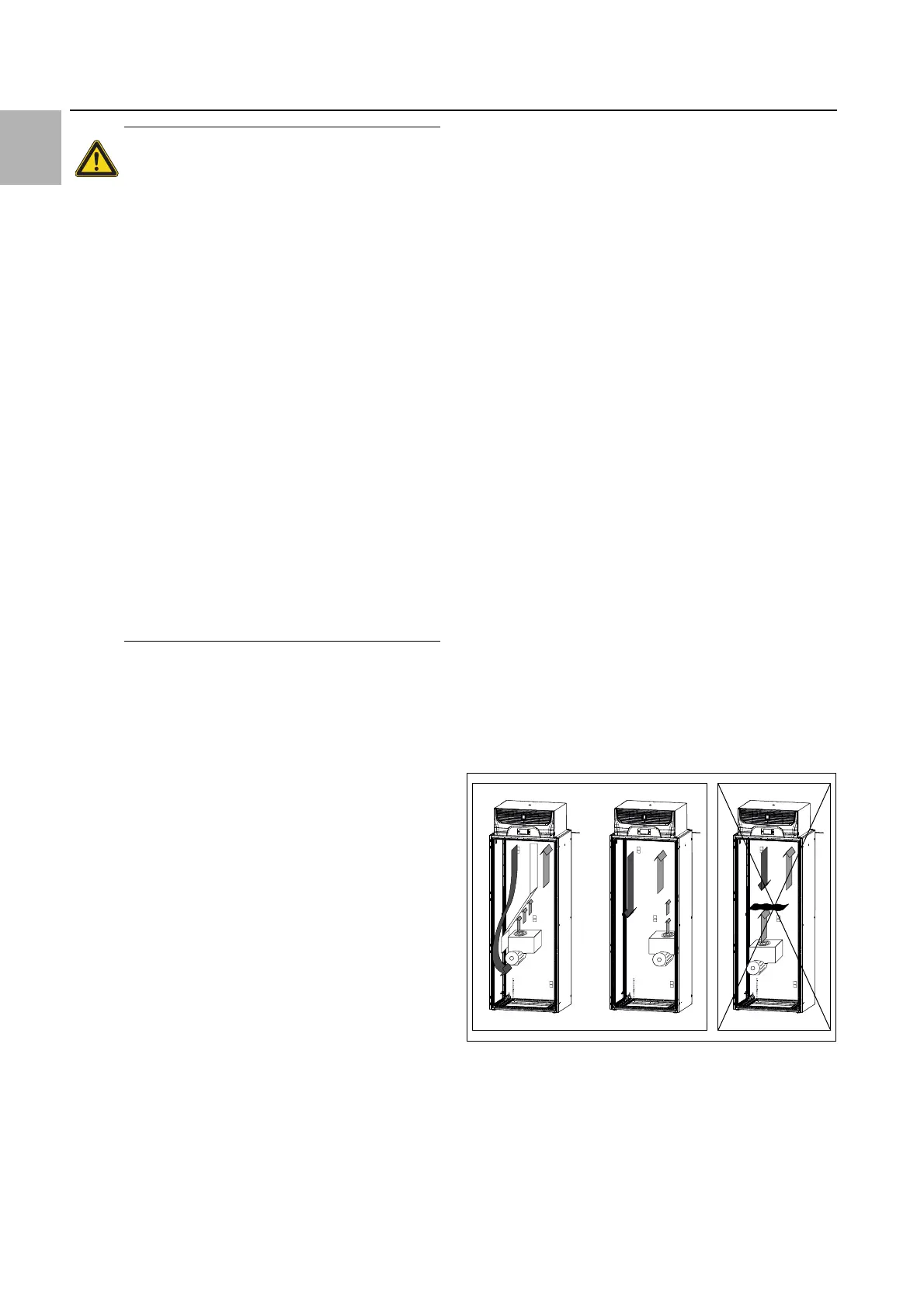
Please ensure that the cold airflow from the cooling
unit is not directed at active components.
Fig. 7: Never direct the cold airflow at active components
(example illustration)
A special baying plate is available as accessory (see sec-
tion13 "Accessories") for baying the integration enclo-
sure onto an enclosure taller than 2000 mm. This baying
plate covers the opening in the upper area of the integra-
tion enclosure so that degree of protection IP 54 is still
guaranteed.
Warning!
Work on electrical systems or equip-
ment may only be carried out by an elec-
trician or by trained personnel under the
guidance and supervision of an electri-
cian. All work must be carried out in ac-
cordance with electrical engineering
regulations.
The cooling unit may only be connected
after the aforementioned personnel have
read this information!
Use only insulated tools.
Follow the connection regulations of the
appropriate electrical supply company.
The cooling unit must be connected to
the mains via an all-pole disconnecting
device to overvoltage category III
(IEC 61058).
The cooling unit is not de-energised until
all of the voltage sources have been dis-
connected!