Rittal roof-mounted Blue e+ cooling unit/VX25 Blue e+ integration solution 33
7 Operation
EN
IPv4
Click on the "IPv4" symbol.
A list of general information about the IPv4 settings will
be displayed.
Page through the list using the "Up" and "Down" ar-
rows.
IPv6
Click on the "IPv6" symbol.
A list of general information about the IPv6 settings will
be displayed.
Page through the list using the "Up" and "Down" ar-
rows.
Click on the desired entries to display the IPv6 ad-
dresses.
7.4.3 Alarm relays
There are two floating relay outputs in the connection
box on the rear of the unit, which may be used to output
system messages from the cooling unit to an external
signal source (see section 5.4.3 "Connect the alarm re-
lays"). The relay outputs may be configured here.
Click on the "Alarm relay" symbol to display a list of
lower-level screen pages.
Switch NO/NC
The switch logic of the relay output, i.e. whether it is to
be used as a normally closed or normally open contact,
may be set here.
Click on the "Switch NO/NC" symbol.
Choose your preferred switch logic by selecting it from
the display.
Confirm your entry with "OK".
List of functions
This is where you specify which error messages should
lead to switching of the respective relay output.
Click on the "Relay 1" or "Relay 2" symbol, and select
the alarm relay to which you wish to assign a function.
From the list of errors, select the function which should
cause the previously selected relay output to switch.
If applicable, assign further functions to the relay out-
put, and the output will then be switch if at least one
of the assigned functions leads to an error message.
Confirm your entry with "OK".
If applicable, configure the other relay output with oth-
er functions.
Parameter Setting
DHCP off/on
IP address xxx.xxx.xxx.xxx
Network
mask
xxx.xxx.xxx.xxx
Router
address
xxx.xxx.xxx.xxx
Tab. 19: IPv4 settings
Parameter Setting
DHCP off/on
IP address 1 …
IP address 2 …
Auto
address
…
Link-local
addr.
…
Tab. 20: IPv6 settings
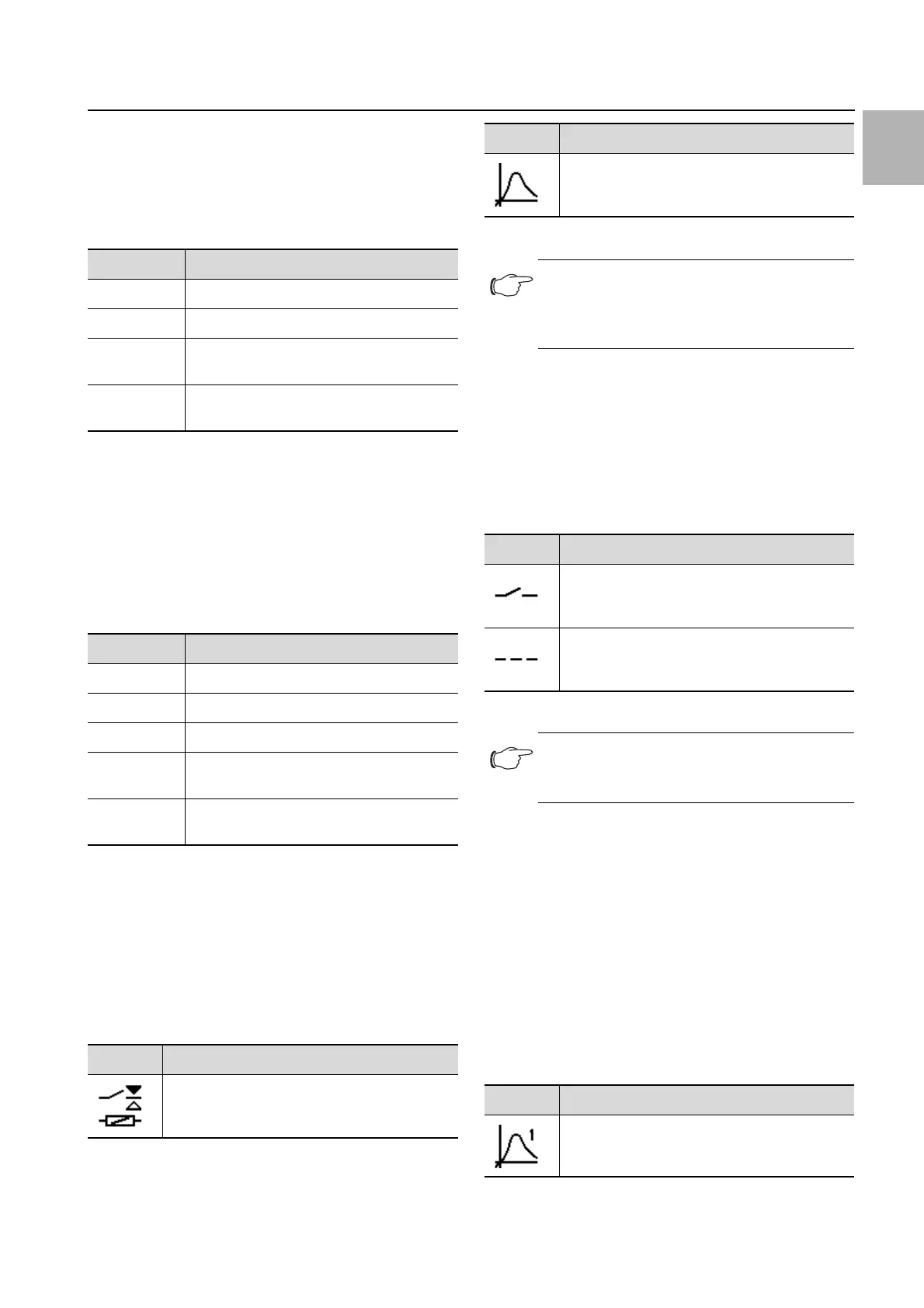
Symbol Parameter
Switch NO/NC
Switch the alarm relay as a normally closed or
normally open contact.
Tab. 21: "Alarm relay" zone
Function list
Allocation of a function to the respective alarm
relay.
Note:
For the factory setting of alarm relay alloca-
tion see section 7.6 "List of system messag-
es" (Tab. 25).
Symbol Parameters
Normally open
Switch the alarm relay as a normally open con-
tact.
Normally closed
Switch the alarm relay as a normally closed
contact.
Tab. 22: Switch logic of the alarm relay
Note:
The factory setting of the relay outputs in their
de-energised state is NO (Normally Open).
Symbol Parameter
Assign relay 1
Tab. 23: List of functions
Symbol Parameter
Tab. 21: "Alarm relay" zone