Page 3/ 24 34-81 10/2013
1. TECHNICAL DATA
Housing: Self-extinguishing ABS.
Case: Facia 100x64 mm; depth 76mm
Mounting: Panel mounting in a 56x72 mm panel cut-out with two screws.
3x2mm. Distance between the holes
40mm
Protection: IP20.
Frontal protection: IP65 with optional frontal gasket mod. RGW-V
Connections: Spade on connectors 6.3 mm for supply and relays and 4÷20mA-
Screw terminals block for probes, digital input
Power supply: 24Vac Class 2
Power absorption: 7VA max.
Display: Dual display
Relay outputs: 3 SPST relay contacts, 3A, 8A resistive load.
Other output: Audible alarm
4÷20mA modulation output
Inputs: 3 NTC probes
Digital inputs: 3 Dry Contact
Hot key facility for fast programming
Serial output: TTL standard
Communication protocol: Modbus - RTU
Data storing: On non-volatile memory (EEPROM).
Internal clock back-up: 24 hours
Kind of action: 1B.
Pollution grade: Normal
Software class: A.
Operating temperature: 32÷140°F (0÷60 °C)
Storage temperature: -13÷140°F (-25÷60 °C)
Relative humidity: 20÷85% (no condensing)
Measuring and regulation range: NTC probe: -58÷230°F (-40÷110°C)
Resolution: 1°F or 1 °C (selectable).
Accuracy (ambient temp. 77°F): ±1 °F ±1 digit
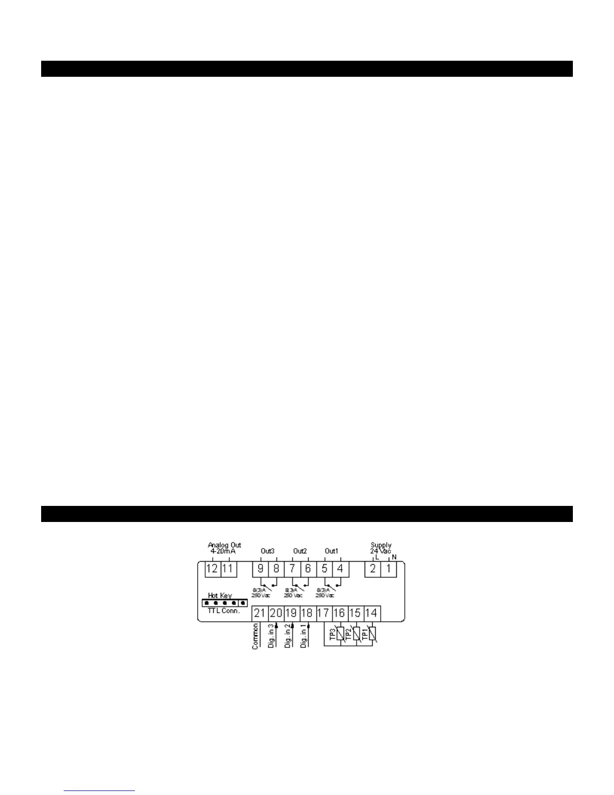
2. WIRING DIAGRAMS