EasyManua.ls Logo

RM Italy KLV 350 - User Manual

RM Italy KLV 350
4 pages
Print Icon
To Next Page IconTo Next Page
Loading...
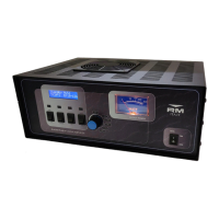
Interruttore generale di rete - Network switch - Interrupteur général
d'alimentation - Hauptschalter - Interruptor general de red.
Interruttore accensione lineare - Linear amplifier switch - Interrupteur
amplificateur linéaire - Schalter für Linearverstärker - Interruptor del
amplificador lineal
Interruttore selezione modo di trasmissione - Transmission mode selection
switch - Interrupteur sélection mode de transmission - Schalter für Einstellung
der Uebertragungsart - Interruptor selección del modo de trasmisión
Selettore potenza d'uscita - Output power selector - Commutateur sélection
puissance de sortie - Endleistungsschalter - Selector de potencia de salida
Variabile di accordo d'uscita - Output arrangement variable capacitor -
Condensateur variable d'accord de sortie - Variabler Ausgangs regler -
Condensador variable para acopliamiento de la salida
Strumento per la misura della potenza d'uscita - Output power wattmeter -
Instrument de mesure de la puissance de sortie - Gerät fuer die Messung der
Ausgangsleistung - Instrumento de medida de la potencia de salida
Indicatore luminoso di potenza e modulazione - Modulation and power light
indicator - Indicateur lumineux de puissance et modulation - Leuchtanzeiger
fuer Betriebsspannung und Modulierung - Indicador luminoso de potencia y
modulación
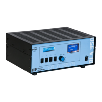
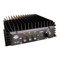
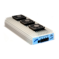
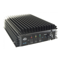
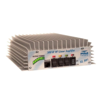
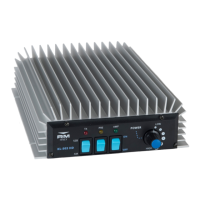
AMPLIFICATORE LINEARE DA STAZIONE BASE
BASE STATION LINEAR AMPLIFIER
AMPLIFICATEUR LINEAIRE
LINEARVERSTÄRKER
AMPLIFICADORES LINEAL
KLV 350
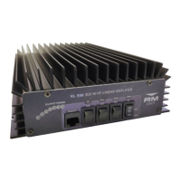
BASE STATION LINEAR AMPLIFIER KLV 350
WATT
ON AIR


OFF StBy AM HI
ON ON
SSB
LOW
TUNE
This is to certify that:
The linear amplifier KLV 350
complies with the provisions of the Directive of the Council of the European Communities on the
approximation of the laws of the Member States relating to electromagnetic compatibility (EMC
Directive 89/336/EEC).
This declaration of conformity of European Communities is the result of an examination carried
out by the Quality Assurance Department of
RM Costruzioni elettroniche
in accordance with European Telecommunicatons Standards ETS 300 684 - 300 339, of December
1995.
ITALY
EC Certificate of conformity
(to EMC Directive 89/336/EEC)
ATTENZIONE !!!! L'apparato è conforme alle norme CE se usato in combinazione con
il filtro 27/586 collegato tra l'uscita a radiofrequenza dell'apparato e l'antenna.
ATTENTION !!!! The item is in compliance with CE regulations if it is used toghether
with 27/586 filter connecting the radio frequency output of the unit an the antenna.
ATTENTION !!!! L'appareil est conforme à la norme CE si utilisé avec le filtre 27/586
uni entre la sortie en radio frequence de l'appareil et l'antenne.
ACHTUNG !!!! Das Gerät entspricht den CE-Prüfnormen solange der Filter 27/586
zwischen HF-Ausgang und Antenne eingeschleift ist.
ATENCION !!!! El apparato es conforme a la norma CE si se utiliza juntamente con el
filtro 27/586 conectado entre la salida a radiofrecuencia del aparado y la antena.
C15
C35
C36
L2
L1
C9
C11
C12
C14
C13
L5
C16
C3
C1
D2
D1
RTX
C2
R1
D3
S1
Tr
C4
C5
C6
C7
C29
S2
Rl
C8
C10
Rla
C31
C32
L3
V1
R2
D6
L8
R8
+
Fan
C30
C33
C34
R9
C28
C17
C18
R4
Lamp2
C19
W
L6
R3
L4
V2
C20
C22
C21
C23
L7
Rlc
D7
D8
S3
C37
C38
Fuse
S4
T
C24
Rlb
Lamp1
C26
D5
D4
R5
R6
R7
C27
C25
Question and Answer IconNeed help?

Do you have a question about the RM Italy KLV 350 and is the answer not in the manual?

Overview

The KLV 350 is a linear amplifier designed for base station use, specifically for users who require high power for long and very long-distance radio connections. Its primary function is to amplify radio frequency (RF) signals, enabling more robust and extended communication.

Function Description:

The KLV 350 operates as a linear amplifier, taking an input RF signal from a transceiver and boosting its power for transmission. It supports various transmission modes, including AM (Amplitude Modulation), FM (Frequency Modulation), SSB (Single Sideband), and CW (Continuous Wave). The amplifier incorporates a fan for forced cooling of the internal tube, allowing for more intensive and prolonged use without overheating.

Key controls and indicators include:

  • Network Switch (1): A general power switch for turning the unit ON or OFF.
  • Linear Amplifier Switch (2): Engages or disengages the linear amplifier function (ON/St.By).
  • Transmission Mode Selection Switch (3): Allows selection of the appropriate mode (AM for AM/FM, SSB for SSB/CW).
  • Output Power Selector (4): Adjusts the amplification level, offering two power levels. The "HI" (maximum) level is recommended for short connections.
  • Output Arrangement Variable Capacitor (TUNE) (5): Used for tuning the amplifier to achieve maximum output power.
  • Output Power Wattmeter (6): Displays the output power in watts.
  • Modulation and Power Light Indicator (7): Illuminates to indicate power and modulates with the signal.

Important Technical Specifications:

  • Frequency Range: 26 - 30 MHz
  • Power Supply: 230 V AC ± 10%
  • Input Energy Consumption: 2.5 A
  • Input Power:
    • AM - FM: 1 - 10 W
    • SSB - CW: 2 - 20 W
  • Output Power:
    • AM - FM: 100 - 200 W
    • SSB - CW: 200 - 400 W
  • Input SWR (ROS ingresso): 1.1 / 1.5
  • Operation Modes: AM, FM, SSB, CW
  • Fuse: 3 A (on the net)
  • Tubes Used: 2 x EL 509 or EL 519

The device is certified to comply with the EC Certificate of Conformity (EMC Directive 89/336/EEC), adhering to European Telecommunications Standards ETS 300 684 and 300 339 (December 1995).

Usage Features:

Installation:

  1. After unpacking, inspect the amplifier for any transport damage.
  2. Connect the transceiver to the SO239 connector labeled "RTX" on the amplifier's rear panel using a 90 cm RG58 extension cable.
  3. Connect the antenna to the "ANT" connector, also on the rear panel.
  4. Ensure the network switch (1) is in the "OFF" position.
  5. Connect the power cable to a suitable outlet, avoiding reducers or adapters.
  6. Position the amplifier to allow easy access to all controls and ensure sufficient free space around it for proper ventilation.

Operation:

  1. Turn on the amplifier using the network switch (1) to "ON."
  2. Allow at least two minutes for the tube to warm up before use.
  3. Select the desired output power level using the selector (4). For short connections, the "HI" (maximum) level is recommended.
  4. Engage the linear amplifier using switch (2) to "ON."
  5. Select the appropriate transmission mode with switch (3): "AM" for AM/FM, "SSB" for SSB/CW.
  6. The Wattmeter (6) will display the output power, and the indicator (7) will illuminate and modulate with the signal.

Tuning (Crucial for optimal performance and tube longevity):

  1. Before making radio connections, the amplifier must be tuned using the TUNE control (5).
  2. Set switch (2) to "ON."
  3. Transmit a signal from your transceiver.
  4. Adjust the TUNE control (5) to achieve maximum power reading on the Wattmeter (6).
  5. During tuning, transmit for no more than 2-3 seconds, with 5-10 second intervals for cooling.
  6. Re-check tuning whenever the channel, frequency, or position of control (4) is changed.

Important Usage Notes:

  • Always disconnect the network plug before opening the amplifier for any maintenance or repair (e.g., fuse replacement).
  • For any problems, consult specialized technicians.
  • To prevent overheating and tube damage, use antennas and cables rated for at least 600 W with an SWR not exceeding 1.5 at maximum power.
  • Use the amplifier for long-distance connections only. Avoid continuous transmissions longer than 5 minutes without reasonable breaks to allow the tube to cool.

Maintenance Features:

  • Warranty: The device comes with a 24-month warranty from the date of receipt.
  • Warranty Exclusions: The warranty does not cover external and aesthetic parts, nor the tubes.
  • Compliance: The manufacturer emphasizes that the use of linear amplifiers is subject to specific laws in each country. Users are advised to be aware of and comply with these regulations. The manufacturer disclaims any responsibility for incorrect use or non-compliance with applicable rules.
  • Voiding Warranty: Failure to observe the instructions provided will void the warranty.

The KLV 350 is designed for robust performance in demanding radio communication scenarios, offering high power output and user-friendly controls, provided the tuning and operational guidelines are strictly followed. Its internal cooling system allows for more intensive use compared to amplifiers without forced cooling.

RM Italy KLV 350 Specifications

General IconGeneral
BrandRM Italy
ModelKLV 350
CategoryAmplifier
LanguageEnglish

Related product manuals