Do you have a question about the RM Italy KL505 and is the answer not in the manual?
Details voltage and current needed for the power supply.
Guide on connecting input/output, power, and antenna.
Steps for setting input power and verifying operation.
Guidance on connecting the amplifier to the radio and a suitable power supply.
Essential checks before powering on, including drive radio output.
Recommended input power and use of the attenuator.
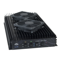
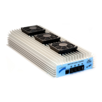
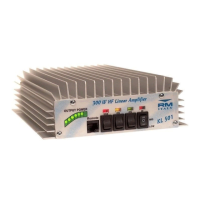
The KL505 is a linear amplifier designed primarily for the HF 10m amateur radio band, specifically operating between 28.000MHz and 29.700MHz. However, it offers useful gain across a broader range of HF bands, from 160m to 10m. This amplifier is capable of handling various narrowband modulation types, including SSB, CW, AM, and FM, as well as SSTV and data modes. It is equipped with four RM SD1446 transistors, contributing to its power output.
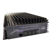
For optimal performance and to prevent damage, proper installation and operation are crucial. The amplifier should be unpacked carefully and inspected for any signs of damage before installation. It requires installation in a location that provides good ventilation to prevent overheating, which can lead to damage. A short, good-quality 50 Ohm patch cable should be used to connect the amplifier's RTX SO239 input connector to the output (antenna socket) of the drive radio. The ANT output connector of the amplifier then connects to the antenna. If an external VSWR/Power meter is used, it should be connected between the amplifier's output and the antenna. It is essential to ensure the antenna is suitably rated for the power output level and that its VSWR does not change significantly with increased power. The antenna should be tuned before connecting the power amplifier or with the amplifier switched off.
The amplifier must be connected to a suitable DC power supply with a correct voltage output and sufficient current rating. The recommended output is 13.6 / 13.8V DC, although the amplifier can operate safely from 12V to 14V DC. The power supply must provide at least 50A continuous current. If the drive radio is also connected to the same power supply, an even higher current rating may be necessary, though connecting the drive radio to a separate supply is generally advised. The cross-sectional area of the cables connecting the amplifier to the power supply should be at least 10mm² or 7 AWG and kept as short as possible to minimize voltage drop. For mobile installations, leads should not exceed 3m and should be connected directly to the auto battery, with an additional inline fuse for protection against short circuits.
A good RF ground system is vital for both RF and AC power supply, enhancing safety and preventing erratic equipment operation due to returned RF. Mobile installations require well-bonded ground connections to the vehicle chassis.
Before operation, users must familiarize themselves with all controls and ensure correct connections. The amplifier features a receive pre-amplifier that can be activated to boost received signal levels, improving intelligibility, especially when signals are weak. This pre-amplifier can be used independently, but it automatically switches out of line when the amplifier is in transmission.
The maximum permissible input power to the amplifier is 10W. It is recommended to adjust the transceiver's RF output power to 5W (or a maximum of 10W) if it is capable of more. Generally, 7W input is sufficient for optimal performance on the 10m band. The amplifier should always be operated at a point below its saturated output to avoid distortion and ensure a cleaner signal. Overdriving the amplifier will not significantly increase signal strength but will lead to higher distortion levels. Running the amplifier slightly under maximum output also helps it run cooler, extending its lifespan.
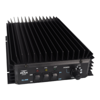
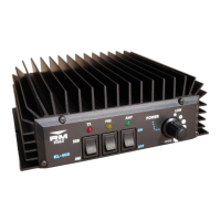
The front panel includes several controls: a Receive Pre-Amplifier ON/OFF Switch, an Amplifier ON/OFF Switch, an Input Attenuator with 6 positions for output power adjustment, and an AM/SSB Switch. Indicator LEDs are present for Pre Amplifier ON, Amplifier ON, and TX (transmission). In SSB mode, the AM/SSB switch adds a short delay to the RTX relays' release time, preventing dropout during speech pauses. For AM or FM modes, the switch should be set to AM.
The input attenuator should only be used to reduce the amplifier's output if needed, not to lower input power if it exceeds 10W, as this can damage the attenuator from overheating. Position 6 provides direct input (no attenuation), while position 1 offers the lowest output power.
The KL505 is not equipped with protection against excessive input power or high VSWR. Therefore, users are responsible for not overdriving the amplifier and ensuring the antenna is correctly tuned. Operating the amplifier into mismatched loads (high VSWR) can reduce efficiency, generate more heat, and potentially cause damage. An acceptable VSWR level is less than 1.5:1, with less than 2.0:1 also acceptable, though some power reduction may occur.
For broadband use on other HF bands, it is essential to connect a suitable Low Pass Filter to the output to suppress harmonic output, prevent interference, and comply with regulations, as the amplifier itself does not feature Low Pass Filtering. The gain of the amplifier increases on lower bands, so less input power may be required for the same output level.
For high duty cycle modes like FM and Data, continuous operation should be avoided to prevent excessive transistor junction temperature. These modes run the amplifier at full power for extended periods, generating more heat than intermittent modes like SSB and CW. Transmission times should be limited to a few minutes, allowing the heatsink to cool down before reuse. The exact safe transmission time depends on factors such as ventilation and ambient temperature.
The manufacturer emphasizes that the use of linear amplifiers is subject to specific laws in each country, and users are solely responsible for knowing and complying with these laws. The manufacturer disclaims any responsibility for unlawful use.
The product comes with a 24-month warranty from the date of purchase, requiring the original purchase receipt for any claim. This warranty does not cover aesthetic damage or damage to the RF power transistors resulting from incorrect use.
| Input power | 1-10 W |
|---|---|
| Input power SSB | 2-20 W |
| Mode | AM/FM/SSB/CW |
| Weight | 1.5 kg |
| Input Impedance | 50 Ohm |
| Output Impedance | 50 Ohm |
| Cooling | Fan |
| Output power | 300 W max |
| Fuse | 12 A |
| Supply | 12-14 VDC |
| Input Voltage | 12-14 VDC |