EasyManua.ls Logo

RM Italy HLA 300 User Manual

RM Italy HLA 300
4 pages
To Next Page IconTo Next Page
Page #1 background imageLoading...
Page #1 background image
Amplificatore Lineare HF Professionale
HF Professional Linear Amplifier
HLA 300
nn
nn
n Commutatore per la selezione della frequenza "banda" di lavoro o per la selezione
automatica gestita dal processore interno - Commutator to select the working
"band" frequency or for an automatic selection from the inner processor.
oo
oo
o Indicatore della frequenza impostata o, se il commutatore
nn
nn
n é in AUT., indica la
frequenza attualmente utilizzata - Selected frequency indicator, when commutator
nn
nn
n is in AUT. it indicate the currently used frequency.
pp
pp
p Strumento indicatore della potenza d'uscita - Output power wattmeter
qq
qq
q Indicatore di stato di protezione - Protection state indicator
rr
rr
r Interruttore accensione lineare - Linear amplifier switch
ss
ss
s Led indicatore d'accensione lineare - Amplifier switching on led indicator
tt
tt
t Commutatore disinserimento attenuatore d'ingresso -Input damper switch
uu
uu
u Indicatore attenuatore d'ingresso disinserito - Imput damper switch-off Led
``
``
` Commutatore inserimento ritardo SSB - SSB delay switch
aa
aa
a Led indicatore di trasmissione - Transmission led indicator
Protection
Warning
HF Professional Linear Amplifier
HLA 300
160
O
15-17
AUT.
10-12
40
20-30
80
P
r
e
w
o
p
u
t
u
t
Frequency selection
OFF OFF
SSB delay
ON HI
TX
+
pp
pp
p
oo
oo
o+
+
ss
ss
s
+
uu
uu
u
+
aa
aa
a
+
qq
qq
q
nn
nn
n
rr
rr
r
tt
tt
t
``
``
`
www.rmitaly.com
Question and Answer IconNeed help?

Do you have a question about the RM Italy HLA 300 and is the answer not in the manual?

RM Italy HLA 300 Specifications

General IconGeneral
Frequency1.8-30 MHz
Power Supply12-14 V DC
Input Power1-10 W
Output Power300 W max
ModesSSB, CW, AM, FM
Weight1.5 kg
Power Output300 W max
Supply Voltage12-14 V DC

Summary

Front Panel Controls and Indicators

Frequency Selection Commutator

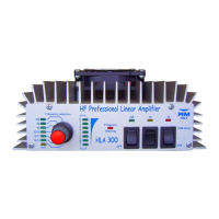
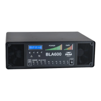
Commutator to select working frequency band or automatic selection.

Frequency Indicator

Shows selected or currently used frequency.

Output Power Wattmeter

Instrument indicating output power.

Protection State Indicator

Indicates protection status.

Linear Amplifier Switch

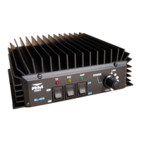
Main switch to turn the linear amplifier on/off.

Amplifier On LED Indicator

LED indicating the amplifier is switched on.

Input Attenuator Switch

Switch to engage or disengage the input attenuator.

Input Attenuator Off LED

LED indicating the input attenuator is off.

SSB Delay Switch

Switch to insert a delay for SSB transmission.

Transmission LED Indicator

LED indicating transmission status.

Description and Features

Harmonic Attenuation Filters

Explains the six low-pass filters for harmonic reduction.

Automatic and Manual Filter Selection

Details microprocessor control for filter selection.

Temperature Protection

Describes the sensor that blocks operation if temperature is excessive.

ROS Protection Circuit

Explains protection against excessive SWR to prevent damage.

Cooling Fans (Model HLA 300V)

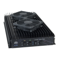
Mentions fans for efficient heat dissipation in specific models.

Installation

Connecting Equipment

Instructions for connecting transceiver and antenna.

Power Supply Requirements

Details voltage, current, and cable specifications.

Ventilation and Placement

Advises on positioning for airflow and access.

Usage and Operation

Transmission Mode and Delay

Explains switch 9 for transmission modes and SSB delay.

Frequency Selection Operation

Details manual/auto selection and error handling.

Protection Warning System

Describes conditions triggering the protection warning indicator.

Resetting Protection

Procedure to manually reset protection after an event.

Transmission Time Limits

Advises on transmission duration for transistor cooling.

Warranty and Legal Notice

Outlines warranty period and manufacturer's disclaimer.

Attention and Safety

Pre-Use Checks

Verify antenna and power supply suitability before use.

Input Signal Level

Requirement to use attenuator for input signals over 12W.

General Precautions

Notes on operational conditions and frequency errors.

Related product manuals