EasyManua.ls Logo

RM Italy BLA 300 User Manual

RM Italy BLA 300
4 pages
To Next Page IconTo Next Page
Page #1 background imageLoading...
Page #1 background image
Amplificatore Lineare HF
HF Linear Amplifier
BLA 300
[[
[[
[ Potenziometro regolazione sintonia preamplificatore - Preamplifier tuning
adjustment
\\
\\
\ Interruttore accensione preamplificatore d' antenna - Antenna preamplifier switch
]]
]]
] Interruttore inserimento ritardo SSB - SSB delay switch
^^
^^
^ Interruttore accensione lineare - Linear amplifier switch
__
__
_ Interruttore inserimento attenuatore d'ingresso -Input attenuator switch
``
``
` Commutatore per la selezione del filtro passa-basso adeguato alla frequenza in uso.
Commutator to select the low-pass filter adapted to the working frequency.
aa
aa
a Led indicatore d'accensione preamplificatore - Preamplifier switching ON led
indicator
bb
bb
b Led indicatore di trasmissione - Transmission led indicator
cc
cc
c Led indicatore d'accensione lineare - Amplifier switching ON led indicator
dd
dd
d Indicatore di stato di protezione (rosso) o attenuatore d'ingresso inserito (verde) -
Protection state indicator (Red) or Input attenuator switch-ON (green)
ee
ee
e Strumento indicatore della potenza d'uscita - Output power wattmeter
ff
ff
f Interruttore generale di rete - Network switch
www.rmitaly.com
rm@rmitaly.com
]]
]]
]
\\
\\
\
``
``
`
^^
^^
^
[[
[[
[
__
__
_
+
aa
aa
a
+
bb
bb
b
+
dd
dd
d
+
cc
cc
c
ee
ee
e
+
ff
ff
f
Main board
?@ABL2
Question and Answer IconNeed help?

Do you have a question about the RM Italy BLA 300 and is the answer not in the manual?

RM Italy BLA 300 Specifications

General IconGeneral
BrandRM Italy
ModelBLA 300
CategoryAmplifier
LanguageEnglish

Summary

Description

Low-Pass Filters

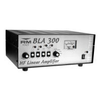
Six filters with cut-off frequencies to eliminate harmonic emissions.

Thermal Sensor Protection

Stops operation if the temperature becomes excessive, with automatic reset.

ROS Protection Circuit

Protects against high SWR or incorrect low-pass filter settings.

Input Power Protection

Protects the amplifier from damage due to excessive input power.

Usage

Input Attenuator Control

Controls input signal level and indicates green LED when active.

SSB Delay Switch

Inserts a 1-1.5 sec delay for antenna relay release in SSB CW.

Low-Pass Filter Selection

Selects the low-pass filter based on the transmission frequency.

Preamplifier Tuning

Tunes the antenna preamplifier for maximum signal intelligibility.

Protection Indicator

Red LED indicates danger, e.g., filter mismatch or high SWR.

ALC Calibration

Calibrates input power for optimal ALC connection.

Installation

Connections

Connects transmitter, antenna, power supply, and ALC/PTT.

Ventilation and Placement

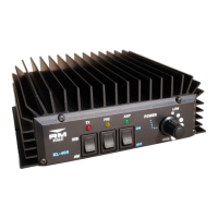
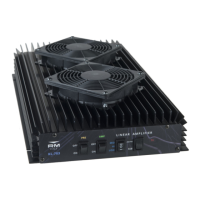
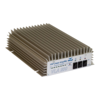
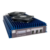
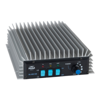
Ensures good airflow around the unit for proper ventilation.

Description (GB)

Low-Pass Filters

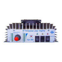
Set of six filters to eliminate harmonic emissions.

Thermal Sensor

Stops operation if temperature increases, resets automatically.

ROS Protection

Stops amplifier if stationary waves (ROS) in antenna are too high.

Input Power Protection

Protects from damages if input power exceeds 12-13 W.

Related product manuals