Do you have a question about the RM Italy BLA600 and is the answer not in the manual?
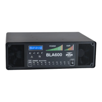
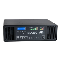
Primary text and status display for the amplifier.
LED bar graphs for output power and SWR levels.
Buttons for navigation, selection, and operation modes.
LEDs indicating amplifier protection status and transmission activity.
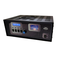
Main ON/OFF switch for AC power input.
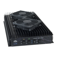
Inlets for cooling air to the RF deck and power supply.
Socket for AC mains connection and the main fuse holder.
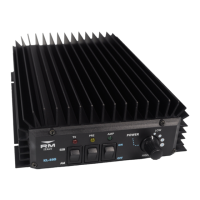
Connectors for ALC adjustment and PTT input signal.
Ports for connecting antennas to the amplifier's outputs and input.
Switch for AC input voltage and grilles for heat exhaust.
Terminal for connecting the amplifier to station RF ground.
Warnings regarding dangerous voltages and user serviceability.
Ensuring connected equipment matches amplifier power output.
Importance of proper grounding and safe antenna placement.
Advice on avoiding fluids, direct sunlight, and abnormal conditions.
Maximum allowable input power for safe operation.
Caution about hot surfaces near cooling exhaust.
Steps for safely removing and inspecting the amplifier after shipping.
Recommendations for placement to ensure ventilation and cooling.
Details on connecting transceiver, antenna, and power.
Procedure for assigning antenna outputs per band.
Recommended initial test setup using a dummy load.
Understanding the amplifier's operational states.
Description of the amplifier's protection against excessive input power.
Critical advice for using ATUs with non-resonant antennas.
List of transmission modes compatible with the amplifier.
Instructions for entering, navigating, and exiting the menu system.
List of available configuration options within the menu.
Configuration for the Automatic Level Control (ALC) output.
Step-by-step guide for setting ALC Max and Min power levels.
Option to select temperature units (Celsius/Fahrenheit).
Adjusting the intensity of the LCD and indicator LEDs.
Adjusting the contrast level of the LCD display.
Enabling the mode for fast CW QSK operation.
Monitoring options during Standby (RX) mode.
Monitoring options during Operate (TX) mode.
Restoring the amplifier to its original factory settings.
Option to exit the menu system and return to standby.
Overview of monitored parameters and rapid reaction protection.
List and explanation of errors occurring during the self-test.
Messages displayed during normal operation faults.
Errors related to excessive input power or out-of-band frequency.
Errors related to SWR, drain current, and voltage levels.
Error indicating a problem with the PIN diode switching circuit.
Explanation of the principles and importance of RF grounding.
Best practices for connecting to RF ground.
Impact of ATUs and BALUNs on grounding and RF performance.
Addressing common RF interference issues in the shack.
Information on warranty coverage, duration, and claims.
Operating frequency bands and optimized Low Pass Filters.
Details on the active device and maximum output power.
Required input power and amplifier power gain.
Impedance matching and types of connectors used.
Supported supply voltages and fuse ratings.
Maximum PA current and monitored parameters.
Specifications for PTT input and ALC output interfaces.
Overall size and weight of the amplifier unit.
| Frequency Range | 1.8-30 MHz |
|---|---|
| Input Power | 1 - 10 W |
| Modes | SSB, CW, AM, FM |
| Output Power | 600 W PEP |
| Power Output | 600 W PEP |