3
Access Keypad Installation Guide
Introduction
Included in this Package
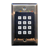
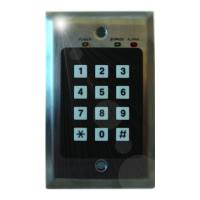
Access Keypad Overview
The access keypad is used by facility staff to temporarily bypass a protected exit, allowing
a tag to enter the exciter field without generating an alarm. The keypad also produces
audible and visual indication of alarm and bypass conditions and visual indication of
power on.
When the door controller is placed in test mode (Position 0, SW102), the keypad can be
used to help tune the exciter field. See “Door Controller and Exciter Installation Proce-
dure” in
Chapter 4 of either the Halo Installation Manual (981-000026-000) or
the RoamAlert Installation Manual (981-000043-000) for details
.
Two installation modes are available (set by JP3 on the back of the keypad):
• Mode 1 (formerly known as PINpad mode).
Up to 1000 unique PIN (Personal Identification Number) codes can be stored in the
door controller and managed at the RoamAlert server PC. In this mode, the Access
Keypad software tracks each code in the Activity Log. Use this mode when the facility
requires a record of which staff member bypassed the exit at a specific date and time.
• Mode 2 (formerly DKY Keypad mode).
This mode uses four generic passcodes, 2 for bypass and 2 for reset. Mode 2 is much
easier for the facility to administer, but it does not provide the detailed tracking and
added security of Mode 1. In Mode 2, only the date and time of each bypass is
recorded in the Activity Log.
QTY PART # Description
1 AR3KY01-030 Access Keypad
1N/A Keypad Cable
1N/A Modular Splitter (for two keypad installations)
1N/A Low voltage retrofit bracket
2N/A Mounting screws
1 981-000018-000 This document
 Loading...