EasyManua.ls Logo

ROBBE RO-CONTROL V2 Series - User Manual

ROBBE RO-CONTROL V2 Series
12 pages
Go to English
Print Icon
To Next Page IconTo Next Page
Loading...
www.robbe.com
DEUTSCH 1
BETRIEBSANLEITUNG
RO-CONTROL V2 MOTORREGLER
Modellsport
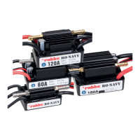
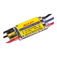
RO-CONTROL 3-40 V2 3-4S -40(60)A BEC Nr.: 8739
RO-CONTROL 4-50 V2 3-4S -50(70)A BEC Nr.: 8738
RO-CONTROL 6- 80 V2 3-6S - 80(100)A SWITCH BEC Nr.: 8736
RO-CONTROL 6-100 V2 3-6S -100(120)A SWITCH BEC Nr.: 8735
Lesen Sie die Anleitungen aller elektronischen Komponenten und des Flugzeugs durch und stellen Sie sicher, dass die
Leistungskonguration angemessen ist, bevor Sie den Drehzahlregler verwenden.
Vergewissern Sie sich, dass alle Kabel und Anschlüsse gut isoliert sind, bevor Sie den Regler mit anderen Komponenten
verbinden, da ein Kurzschluss Ihren Regler beschädigen kann. Stellen Sie sicher, dass alle Komponenten ordnungsge-
mäß angeschlossen sind, um schlechte Verbindungen zu vermeiden, die dazu führen können, dass Ihr Flugzeug die
Kontrolle verliert oder andere unvorhersehbare Probleme wie Schäden am Gerät auftreten. Falls erforderlich, verwen-
den Sie bitte einen Lötkolben mit ausreichender Leistung, um alle Eingangs-/Ausgangskabel und Stecker anzulöten.
Achten Sie darauf, dass der Motor während der Rotation nicht blockiert, da sonst der Regler zerstört und auch der
Motor beschädigt werden kann. (Hinweis: Bringen Sie den Gasknüppel in die untere Position oder trennen Sie sofort
den Akku, wenn der Motor wirklich blockiert wird).
Benützen Sie dieses Produkt niemals bei extrem heißem Wetter und verwenden Sie es nicht weiter, wenn es sehr heiß
wird. Hohe Temperaturen können den Überhitzungsschutz des Reglers aktivieren oder den Regler sogar beschädigen.
Trennen Sie den Akku nach dem Gebrauch immer ab und entfernen Sie ihn, da der Regler weiterhin Strom ver-
braucht, wenn er noch an den Akku angeschlossen ist. Ein längerer Betrieb führt zu einer vollständigen Entladung des
Akkus und damit zu einer Beschädigung des Akkus und/oder des Reglers. Dies fällt nicht unter Garantie.
01. WARNHINWEISE
03. TECHNISCHE DATEN
04. ANLEITUNG
Signal Kabel Beschreibung:
Gassignalkabel (Weiß/Rot/Schwarzes dreifarbiges Kabel): Schließen Sie es an das Gassignal des Empfän-
gers oder Flugreglers an. Der weiße Draht ist für die Übertragung von Gassignalen, die roten und schwar-
zen Drähte sind BEC-Ausgangsdrähte.
Rückwärts Brems-Signalkabel (gelbes Kabel): muss in einem beliebigen freien Kanal des Empfängers
eingesteckt werden (bei Verwendung des Rückwärts Bremsmodus), um das Ein- und Ausschalten der
Rückwärts Bremsfunktion zu steuern.
Programmierkabel (gelbes Kabel): Schließen Sie es an eine LED-Programmierbox an, wenn Sie den Regler
programmieren möchten.
Model
Dauer-
strom
Max.
Strom
BEC Ausgang
Eingangs-
spannung
Gewicht Größe (L x B x H)
RO-CONTROL V2 40A 40 A 60 A 5V @ 5A (Switch-mode) 3–4S LiPo 36 g 60x25x8 mm
RO-CONTROL V2 50A 50 A 70 A 5V @ 5A (Switch-mode) 3–4S LiPo 36 g 60x25x8 mm
RO-CONTROL V2 80A 80 A 100 A 5V @ 7A (Switch-mode) 3–6S LiPo 79 g 85x36x9 mm
RO-CONTROL V2 100A 100 A 120 A 5V @ 7A (Switch-mode) 3–6S LiPo 92 g 85x36x9 mm
Vielen Dank, dass Sie sich für dieses Robbe Modellsport
Produkt entschieden haben! Bürstenlose Antriebssysteme
können sehr gefährlich sein. Jede unsachgemäße Ver-
wendung kann zu Verletzungen und Schäden am Produkt
und an den damit verbundenen Komponenten führen.
Wir empfehlen dringend, diese Bedienungsanleitung vor
dem Gebrauch durchzulesen. Da wir keine Kontrolle über
die Verwendung, Installation oder Wartung dieses Produkts haben,
können wir keine Haftung für Schäden oder Probleme überneh-
men, die durch die Verwendung des Produkts entstehen. Wir über-
nehmen keine Verantwortung für Schäden, die durch nicht autori-
sierte Änderungen an unserem Produkt entstehen. Darüber hinaus
behalten wir uns das Recht vor, unser Produkt in Bezug auf Design,
Aussehen, Eigenschaften und Nutzungsanforderungen ohne Vo-
rankündigung zu ändern. Wir, Robbe Modellsport, sind nur für un-
sere Produktkosten verantwortlich und übernehmen keine Haftung
für Schäden, die durch die Nutzung unseres Produktes entstehen.
Achtung! Der Standard-Gasbereich dieses Reglers ist von 1100µs bis 1940µs (Futaba-Standard); Benutzer müs-
sen den Gasbereich kalibrieren, bevor Sie einen neuen Ro-Control V2 Brushless ESC an einem anderen Sender
verwenden.
Schalten
Sie den
Sender
ein und
bringen Sie
den Gas-
knüppel in
die oberste
Position.
ATTENTION
CAUTIONS
Drehzahlregler, welcher über einen leistungsstarken 32-Bit-Mikroprozessor (mit einer Betriebsfrequenz von bis zu 96 MHz)
verfügt und mit verschiedenen bürstenlosen Motoren kompatibel ist.
Die DEO-Technologie (Driving Efciency Optimization) verbessert die Gasannahme und die Efzienz erheblich und
reduziert die Temperatur des Reglers.
Separates Programmierkabel zum Anschluss des Reglers an eine LED-Programmierbox ermöglicht dem Benutzer, den
Regler jederzeit und überall zu programmieren. (Detaillierte Informationen nden Sie in der Bedienungsanleitung der
Robbe Modellsport LED-Programmierbox).
Normal-/Rückwärts Bremsmodi (insbesondere der Rückwärts Bremsmodus) können die Landestrecke des Flugzeugs
effektiv verkürzen.
Der Suchmodus kann dem Benutzer helfen, das Flugzeug durch Alarmtöne zu nden, nachdem es abgestürzt ist.
Mehrere Schutzfunktionen wie Überhitzungsschutz, Gas-Signalverlust, Überlastungsschutz usw. verlängern effektiv die
Lebensdauer des Reglers.
02. EIGENSCHAFTEN
ATTENTION
1 ANSCHLÜSSE
2 DREHZAHLREGLER KALIBRIERUNG
Schließen Sie
einen Akku
an den Reg-
ler an; der
Motor gibt
ein „♪ 123“
von sich, um
anzuzei-
gen, dass
der Regler
normal
eingeschal-
tet ist.
Dann gibt
der Motor
zwei kurze
Pieptöne
ab, um
anzuzeigen,
dass der
Endpunkt
der ma-
ximalen
Gasposition
akzeptiert
wurde.
Bewegen Sie den
Gassteuerknüp-
pel innerhalb von
5 Sekunden nach
den zwei kurzen
Pieptönen in die
unterste Position,
die minimale
Gasposition wird
1 Sekunde später
akzeptiert.
Der Motor
piept „1-6“,
um die An-
zahl der ein-
gesteckten
LiPo-Zellen
anzuzeigen.
Der Motor
gibt einen
langen
Signalton
ab, um
anzuzei-
gen, dass
die Kali-
brierung
abge-
schlossen
ist.
Schalten Sie
den Sender ein
und bringen Sie
den Gasknüp-
pel in die unter-
ste Position.
Nachdem der Regler an
einen Akku angeschlos-
sen wurde, zeigt der Mo-
tor mit einem „♪ 123“ an,
dass der Regler normal
eingeschaltet ist.
Der Motor gibt
mehrere Pieptöne
ab, um die Anzahl
der LiPo-Zellen
anzuzeigen.
Der Motor gibt
einen langen
Piepton von sich,
um anzuzeigen,
dass der Regler
betriebsbereit ist.
3 NORMALER STARTVORGANG
Question and Answer IconNeed help?

Do you have a question about the ROBBE RO-CONTROL V2 Series and is the answer not in the manual?

Overview

The Robbe RO-CONTROL V2 ESC is a high-performance brushless motor speed controller designed for model aircraft. It features a 32-bit microprocessor operating at up to 96MHz, ensuring compatibility with various brushless motors.

Function Description:

The ESC is designed to regulate the speed of brushless motors in model aircraft, offering precise control and efficient operation. It incorporates DEO (Driving Efficiency Optimization) Technology, which significantly improves throttle response and overall driving efficiency while simultaneously reducing the ESC's operating temperature.

The ESC supports both Normal and Reverse brake modes. The Reverse brake mode, in particular, can effectively shorten the landing distance of the aircraft. A dedicated yellow signal wire for the Reverse Brake function must be plugged into any vacant channel on the receiver to control its activation and deactivation. The motor direction can be controlled via this channel, with a range of 0-50% for default motor direction and 50-100% for counterclockwise rotation. The Linear Reverse Brake mode offers a more nuanced control, with the initial throttle value set at 10% and the throttle stroke cured to 1.34ms-1.79ms.

For programming, the ESC can be connected to an LED program box via a separate yellow programming cable. This allows users to program the ESC anytime and anywhere, offering flexibility in adjusting parameters. Alternatively, the ESC can be programmed directly using the transmitter stick, following a four-step process: entering programming, selecting parameter items, selecting parameter values, and exiting programming.

The ESC includes a "Search Mode" feature, which helps users locate a crashed aircraft by emitting alarm beeps from the motor when the throttle is at 0% and continues for a set duration (5, 10, or 15 minutes).

Important Technical Specifications:

The RO-CONTROL V2 ESC series comes in several variants, each with specific current ratings and LiPo cell compatibility:

  • RO-CONTROL V2 40A:
    • Continuous Current: 40 A
    • Peak Current: 60 A
    • BEC Output: 5V @ 5A (Switch-mode)
    • Input Voltage: 3-4S LiPo
    • Weight: 36 g
    • Size (L x W x H): 60x25x8 mm
  • RO-CONTROL V2 50A:
    • Continuous Current: 50 A
    • Peak Current: 70 A
    • BEC Output: 5V @ 5A (Switch-mode)
    • Input Voltage: 3-4S LiPo
    • Weight: 36 g
    • Size (L x W x H): 60x25x8 mm
  • RO-CONTROL V2 80A:
    • Continuous Current: 80 A
    • Peak Current: 100 A
    • BEC Output: 5V @ 7A (Switch-mode)
    • Input Voltage: 3-6S LiPo
    • Weight: 79 g
    • Size (L x W x H): 85x36x9 mm
  • RO-CONTROL V2 100A:
    • Continuous Current: 100 A
    • Peak Current: 120 A
    • BEC Output: 5V @ 7A (Switch-mode)
    • Input Voltage: 3-6S LiPo
    • Weight: 92 g
    • Size (L x W x H): 85x36x9 mm

The default throttle range is 1100µs to 1940µs (Futaba standard). Users must calibrate the throttle range when using a new ESC or a different transmitter.

Usage Features:

  • Throttle Calibration: Essential for initial setup. The process involves turning on the transmitter with the throttle stick at the top position, connecting the battery to the ESC, waiting for specific beeps, then moving the throttle stick to the bottom position.
  • Start-up Mode: Adjustable to Normal, Soft, or Very Soft, corresponding to throttle response times of approximately 200ms, 500ms, and 800ms respectively, for acceleration from 0% to 100%.
  • Timing: Allows adjustment of the drive motor timing to Low (5°), Medium (15°), or High (25°).
  • Active Freewheeling (DEO): Enabled by default, this feature can be disabled. When enabled, it provides better throttle linearity and a smoother throttle response.
  • LiPo Cells Detection: The ESC can automatically calculate the number of LiPo cells based on a 3.7V/Cell rule ("Auto Calc") or allows manual setting.
  • Cutoff Voltage: If disabled, the low-voltage protection is off. Otherwise, it can be set to Low (2.8V/cell), Medium (3.0V/cell), or High (3.4V/cell). The total protection voltage is calculated by multiplying this value by the number of LiPo cells.
  • Voltage Cutoff Type: Offers "Soft Cutoff" (gradually reduces output to 60% over 3 seconds) or "Hard Cutoff" (immediately cuts off output).
  • Brake Force: Adjustable to Low (60%), Medium (90%), or High (100%) in Normal Brake mode.

Maintenance Features:

The ESC incorporates multiple protection features to prolong its service life:

  • Start-up Protection: Monitors motor speed during start-up. If speed increase is unstable or stops, the ESC considers it a start-up failure. It attempts to restart automatically if throttle is below 15% or requires manual reset if above 20%.
  • ESC Thermal Protection: Gradually reduces output (up to 60% of full power) when the ESC temperature exceeds 120°C, rather than cutting off power completely, to prevent crashes.
  • Throttle Signal Loss Protection: Cuts off output immediately if signal loss is detected for over 0.25 seconds, resuming output when normal signals are received.
  • Overload Protection: Cuts off power or restarts automatically if the load suddenly increases to a very high value (e.g., blocked propellers).
  • Low Voltage Protection: Triggers when battery voltage falls below the set cutoff voltage. Depending on the cutoff type (soft or hard), output is reduced or cut off.
  • Abnormal Voltage Input Protection: Triggers if the battery voltage is outside the supported input voltage range.

For troubleshooting, the manual provides a table of warning tones, causes, and solutions for common issues such as incorrect input voltage, no throttle signal, narrow throttle range, ESC thermal protection, and low-voltage cutoff protection.

Regular checks of the ESC's function and external condition are recommended. The connection cables should not be extended, as this can lead to malfunctions. The device is covered by a 24-month warranty, provided it is used according to instructions and with recommended accessories.

ROBBE RO-CONTROL V2 Series Specifications

General IconGeneral
BrandROBBE
ModelRO-CONTROL V2 Series
CategoryController
LanguageEnglish

Related product manuals