www.robbe.com
ENGLISH 5
USER MANUAL
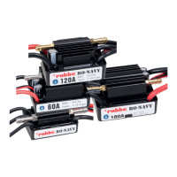
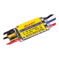
RO-CONTROL V2 ESC
Modellsport
RO-CONTROL 3-40 V2 3-4S -40(60)A BEC Nr.: 8739
RO-CONTROL 4-50 V2 3-4S -50(70)A BEC Nr.: 8738
RO-CONTROL 6- 80 V2 3-6S - 80(100)A SWITCH BEC Nr.: 8736
RO-CONTROL 6-100 V2 3-6S -100(120)A SWITCH BEC Nr.: 8735
• Read through the manuals of all power devices and aircraft and ensure the power conguration is rational before
using this unit.
• Ensure all wires and connections are well insulated before connecting the ESC to related devices, as short circuit will
damage your ESC . Ensure all devices are well connected, in order to prevent poor connections that may cause your
aircraft to lose control or other unpredictable issues like damage to the device. If necessary, please use a soldering
iron with enough power to solder all input/output wires and connectors.
• Never get the motor locked up during high-speed rotation, otherwise the ESC may get destroyed and may also get
your motor damaged. (Note: move the throttle stick to the bottom position or disconnect the battery immediately if
the motor really gets locked up.)
• Never use this unit in the extremely hot weather or continue to use it when it gets really hot. Because high temperature
will activate the ESC thermal protection or even damage your ESC.
• Always disconnect and remove batteries after use, as the ESC will continue to consume current if it`s still connected
to batteries. Long-time contact will cause batteries to completely discharge and result in damage to batteries or/and
ESC. This will not be covered under warranty.
01. WARNINGS
03. SPECIFICATIONS
04. USER GUIDE
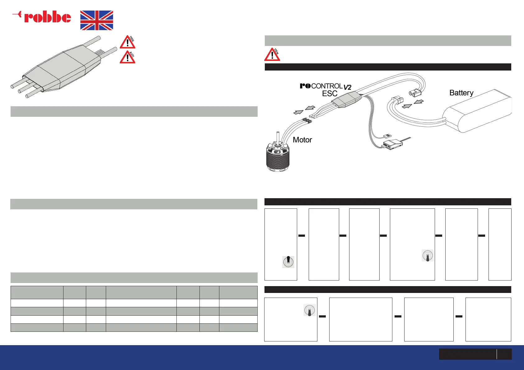
Signal cable description:
Throttle Signal Cable (White/Red/Black Tri-color Cable): plug it into the TH channel on the receiver or ight
controller. The White wire is for transmitting throttle signals, the Red & Black wires are BEC output wires.
Reverse Brake Signal Wire (Yellow Wire): it must be plugged into any vacant channel on the receiver
(when using the Reverse Brake mode) to control the ON/OFF of the Reverse Brake function.
Programming Cable (Yellow Cable): connect it to a LED program box if users want to program the ESC.
Model (Regular)
Cont.
Current
Peak
Current
BEC Output
Input
Voltage
Weight Size (L x W x H)
RO-CONTROL V2 40A 40 A 60 A 5V @ 5A (Switch-mode) 3–4S LiPo 36 g 60x25x8 mm
RO-CONTROL V2 50A 50 A 70 A 5V @ 5A (Switch-mode) 3–4S LiPo 36 g 60x25x8 mm
RO-CONTROL V2 80A 80 A 100 A 5V @ 7A (Switch-mode) 3–6S LiPo 79 g 85x36x9 mm
RO-CONTROL V2 100A 100 A 120 A 5V @ 7A (Switch-mode) 3–6S LiPo 92 g 85x36x9 mm
Thank you for purchasing this Robbe Modellsport pro
-
duct! Brushless power systems can be very dangerous.
Any improper use may cause personal injury and dama-
ge to the product and related devices. We strongly re-
commend reading through this user manual before use.
Because we have no control over the use, installation, or
maintenance of this product, no liability may be assumed for any
damages or losses resulting from the use of the product. We do not
assume responsibility for any losses caused by unauthorized modi-
cations to our product. Besides, we have the right to modify our
product design, appearance, features and usage requirements
without notication. We, Robbe Modellsport, are only responsible
for our product cost and nothing else as result of using our product.
Attention! The default throttle range of this ESC is from 1100µs to 1940µs (Futaba’s standard); users need to
calibrate the throttle range when they start to use a new Ro-Control V2 brushless ESC or another transmitter.
Turn on the
transmitter
and move
the throttle
stick to
the top
position.
ATTENTION
CAUTIONS
• ESC which features a high performance 32-bit microprocessor (with a running frequency of up to 96MHz) is compati-
ble with various brushless motors.
• DEO (Driving Efciency Optimization) Technology greatly improves throttle response & driving efciency and reduces
ESC temperature.
• Separate programming cable for connecting ESC to a LED program box and allows users to program the ESC
anytime, anywhere. (For detailed info, please refer to the user manual of Robbe Modellsport LED program box.)
• Normal/Reverse brake modes (esp. reverse brake mode) can effectively shorten the landing distance for the aircraft.
• Search mode can help users nd the aircraft by the alarm beeps after the aircraft falls into the complex environment.
• Multiple protection features like start-up, ESC thermal, capacitor thermal, over-current, over-load, abnormal input
voltage and throttle signal loss effectively prolong the service life of the ESC.
02. FEATURES
ATTENTION
1 CONNECTIONS
2 ESC/RADIO CALIBRATION
Connect
a battery
to the ESC;
the motor
will sound
“♪ 123” to
indicate
the ESC is
normally
powered
on.
Then the
motor
will beep
two short
beeps to
indicate
the
maximum
throttle
endpoint is
accepted.
Move the throttle
stick to the
bottom position
within 5 seconds
after the two
short beeps, the
minimum
throttle po-
sition will be
accepted 1
second later.
The motor
will beep
“Number”
beeps to
indicate the
number of
LiPo cells
you have
plugged in.
The
motor
will beep
a long
beep to
indicate
the cali-
bration is
comple-
te.
► ► ► ► ►
Turn on the
transmitter, and
then move the
throttle stick
to the bottom
position.
After connected the ESC
to a battery, the motor
will emit “♪ 123” indica-
ting the ESC is normally
powered on.
The motor will emit
several beeps
to indicate the
number of LiPo
cells.
The motor emits
a long beep to
indicate the ESC
is ready to go.
► ► ►
3 NORMAL START-UP PROCESS
 Loading...