8-2
GOVERNOR
ADJUSTMENT
The governor linkage should be adjusted, after reassemble it according to the following procedures.
1)
Connect governor rod and rod spring to carburetor throttle lever and governor lever, then install these to governor
shaft.
NOTE: Never tighten adjusting plate set screw at
this
time, and do not fixed adjusting plate, governor lever and governor
shaft
2)
Connect governor lever and control lever with governor spring, and install control lever on crankcase.
8-2-1
IN
CASE
OF
MODELS
EC10,
EC17
(See
Figs.
8-2-1,8-2-2
and
8-2-3.)
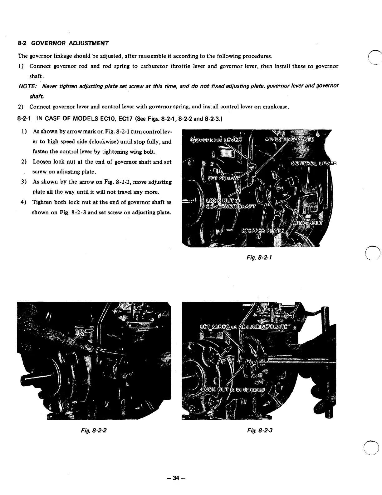
As
shown by arrow mark
on
Fig.
8-2-1
turn control lev-
er to
high
speed side (clockwise) until stop fully, and
fasten the control lever
by
tightening wing bolt.
Loosen lock nut at the end
of
governor shaft and set
screw on adjusting plate.
As
shown
by
the
arrow
on
Fig.
8-2-2,
move adjusting
plate
all
the way until it will not travel
any
more.
Tighten both lock nut at the end
of
governor shaft as
shown on
Fig.
8-2-3
and set screw on adjusting plate.
Fig.
8-2-1
Fig, 8-2-2
Fig.
8-2-3
-34-