5-4-8
BREATHER VALVE
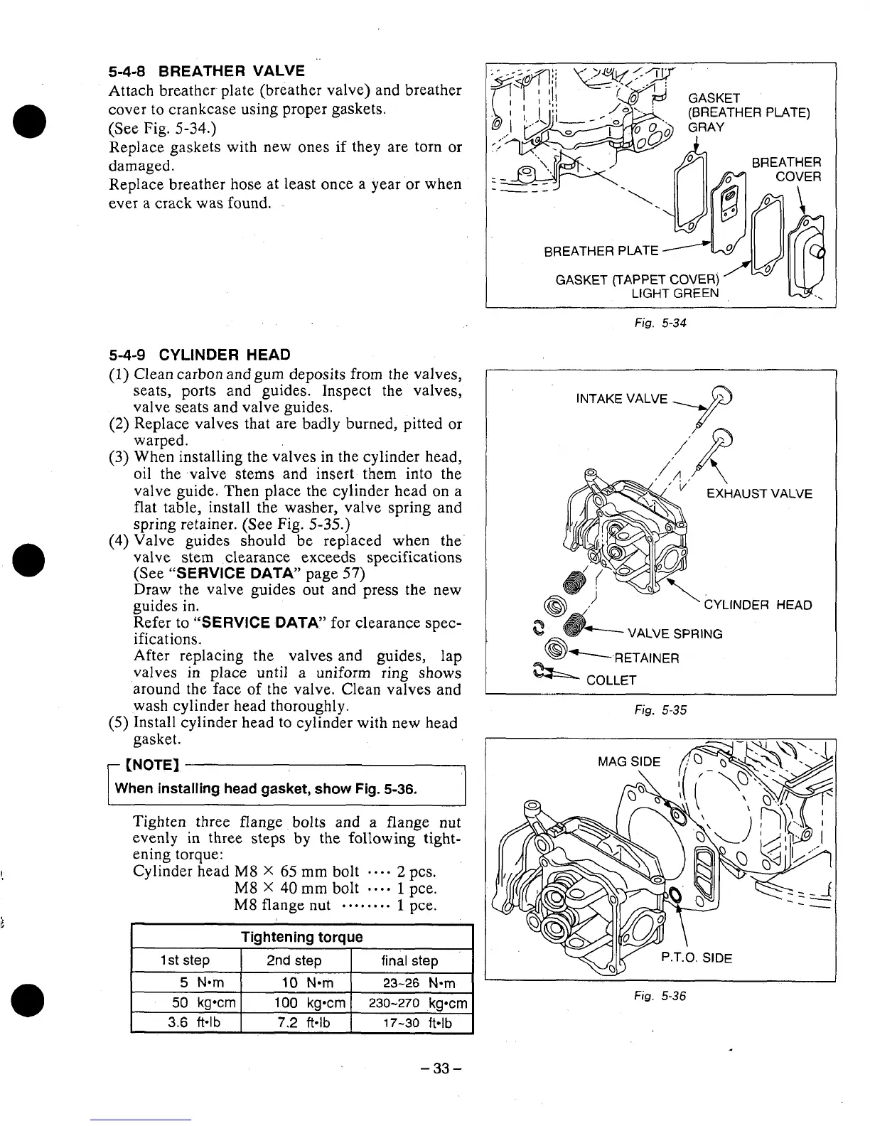
Attach breather plate (breather valve) and breather
cover
to
crankcase
using
proper gaskets.
(See Fig.
5-34.)
Replace gaskets with new ones if they are torn
or
damaged.
Replace breather hose at least once a year or when
ever
a
crack was found.
5-4-9
CYLINDER HEAD
(1)
Clean carbon and gum deposits from the valves,
seats, ports and guides. Inspect
the
valves,
valve seats and valve guides.
(2)
Replace valves that are badly burned, pitted
or
warped.
(3)
When installing the valves
in
the cylinder head,
oil the valve stems and insert them
into
the
valve guide. Then place the cylinder head on a
flat table, install the washer, valve spring and
spring retainer. (See Fig.
5-35.)
(4)
Valve guides should be replaced when the
valve stem clearance exceeds specifications
(See
“SERVICE DATA’
page
57)
Draw the valve guides out and press the new
guides
in.
Refer
to
“SERVICE DATA”
for clearance spec-
ifications.
After replacing the valves and guides, lap
valves
in
place until a uniform ring
shows
around the face
of
the valve. Clean valves and
wash cylinder head thoroughly.
(5)
Install cylinder head to cylinder with new head
gasket.
r
When installing head gasket, show Fig.
5-36.
Tighten three flange bolts and
a
flange nut
evenly
in
three steps
by
the following tight-
ening torque:
Cylinder head
M8
X
65
mm bolt
...-
2
pcs.
M8
X
40
mm bolt
-.*-
1
pce.
M8
flange nut
. e.. .. ..
1
pce.
Tightening
torque
1
st
step
2nd
step
final
step
10
N-m
23-26
Nom
Fig.
5-34
INTAKE
VALVE
Fig.
5-35
50
kgocrn
100
kgocrn
230-270
kgmn
3.6
ft*lb
7.2
ft-lb
17-30
ft*lb
-33-