5-4-19
AIR CLEANER
(1)
Install cleaner base
on
studs, install bracket, cleaner
.I
Tighten the clamp.for stop switch wire together w
M6
Nut
**..
~PCS.
Tightening torque
8-9.5
N*m
80-1
00
kgcm
[NOTE]
Attach the air cleaner gasket to the carburetor
flange when installing air cleaner base
on
the
engine. (See Fig.
5-43.)
ith cleaner bracket
on
crankcase side.
SLOW
AIR
BLEED
JET
AIR
VENT
HOLE
MAIN
AIR
BLEED
JET
(2)
Install cover and element to the air cleaner base.
(3)
Connect a breather pipe between breather and air cleaner.
I
M6
wing bolt lpce.
Fig.
5-43
5-4-20
GOVERNOR
ADJUSTMENT
For correct Carburetor throttle opening and gov-
ernor regulation, the governor lever must be pro-
perly adjusted.
(1)
Install throttle lever ,control linkage on gov-
ernor lever and choke shaft control rod in
choke lever.
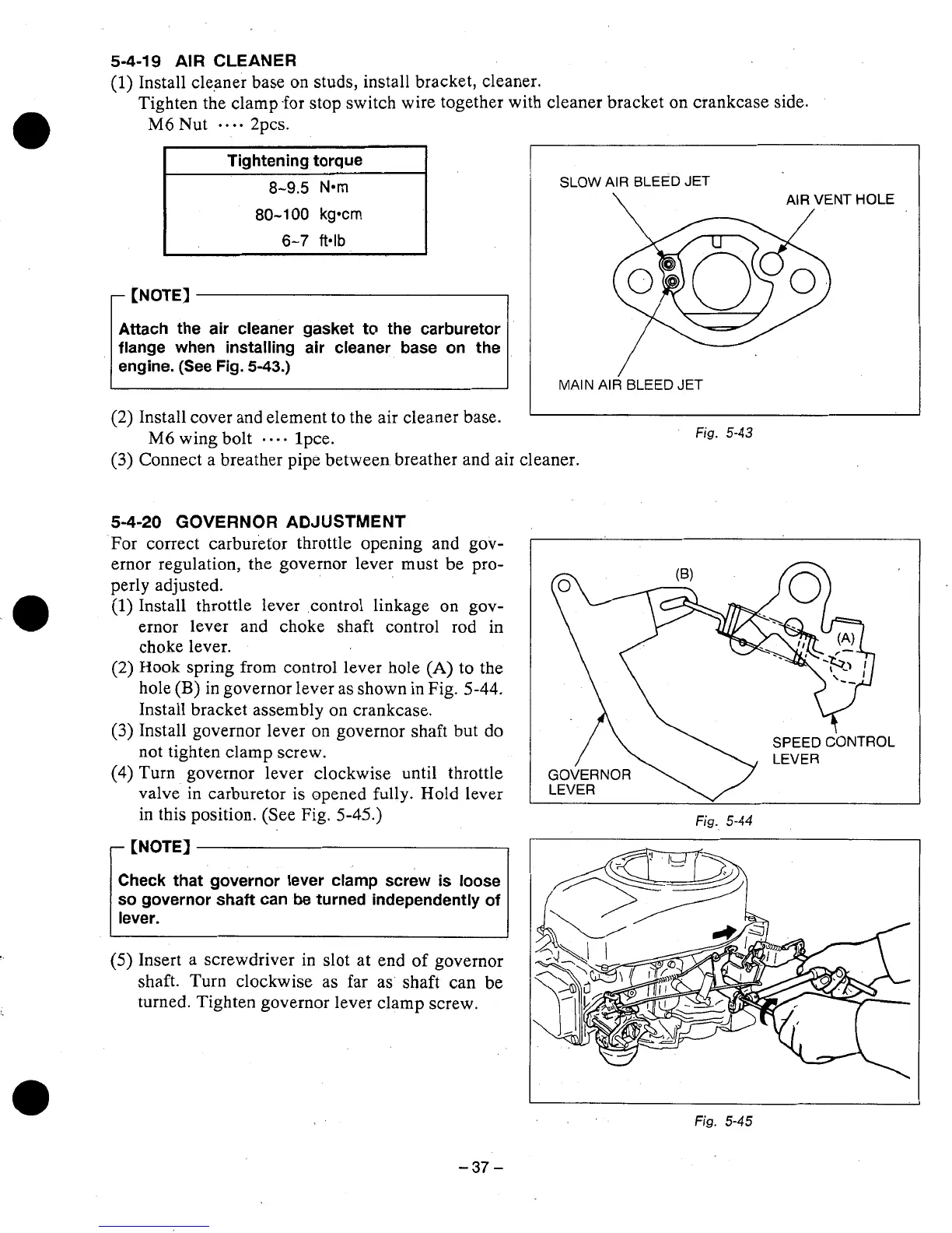
(2)
Hook
spring from control lever hole
(A)
to the
hole
(B)
in governor lever as shown in Fig.
5-44.
Install bracket assembly
on
crankcase.
(3)
Install governor lever
on
governor shaft but do
not tighten clamp screw.
(4)
Turn governor lever clockwise until throttle
valve.
in
carburetor
is
opened
fully.
Hold lever
in this position. (See Fig.
5-45.)
Check that governor lever clamp screw is loose
so
governor shaft
can
be turned independently
of
(5)
Insert a screwdriver in slot at end
of
governor
shaft. Turn clockwise as far as shaft can be
turned. Tighten governor lever clamp screw.
Fig.
5-44
Fig.
5-45
-37-