4-6
VALVE ARRANGEMENT
The intake valve is located at flywheel side
of
the
Hard alloy valve seats are molded in the cylinder
'
cylinder head.
II
n
head and stellite is fused to the exhaust valve face.
The cylinder baffle leads cooling air to the exhaust
valve area for the optimum cooling.
(See
Fig.
4-6.)
EXHAUST
Vi
Fig.
4-6
4-7
CYLINDER HEAD
The cylinder head ,is an aluminum die casting,.
which utilizes wedge type combustion chamber for
the highest combustion efficiency.
(See Fig.
4-7.)
Fig.
4-7
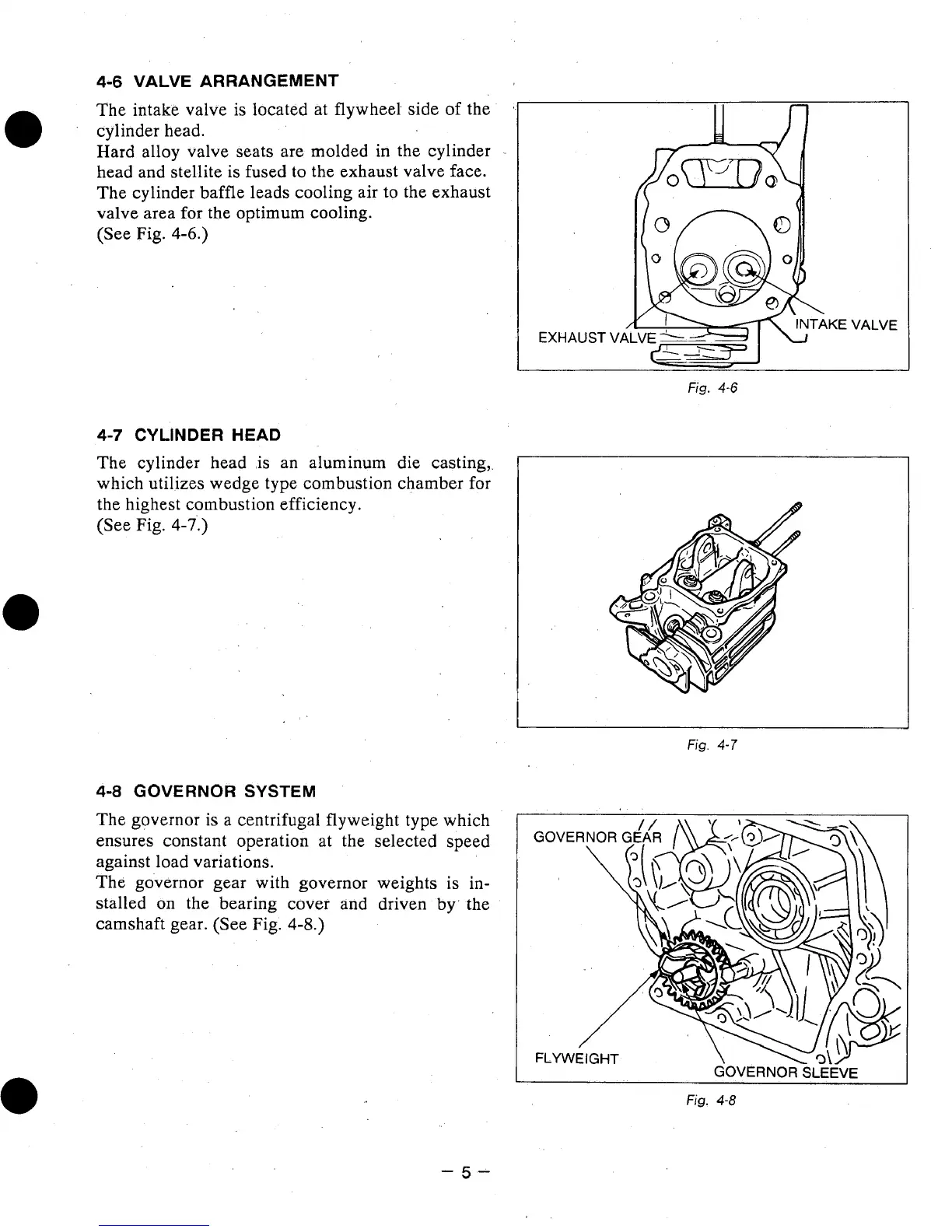
4-8
GOVERNOR SYSTEM
The governor is a centrifugal flyweight type which
ensures constant operation at the selected speed
against load variations.
The governor gear with governor weights is in-
stalled on the bearing cover and driven
by'
the
camshaft gear. (See Fig.
4-8.)
Fig.
4-8
-5-