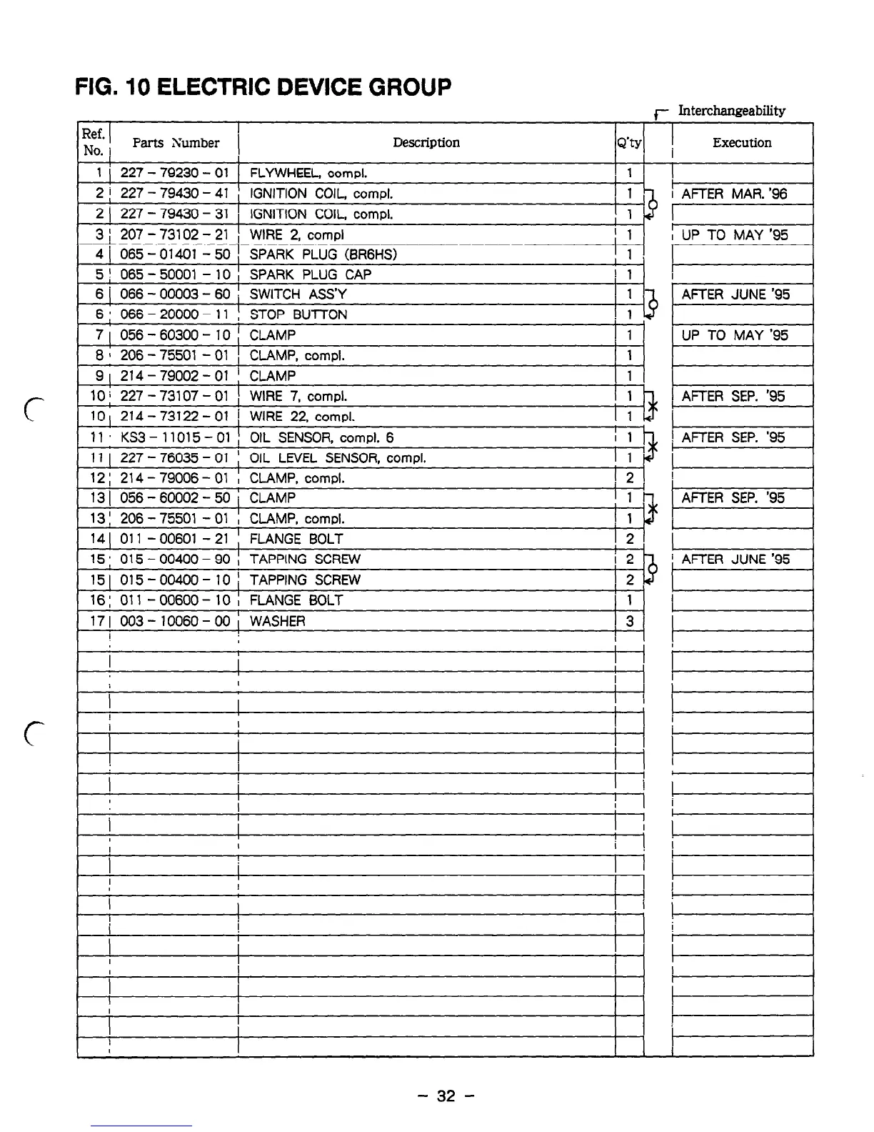
FIG. 10 ELECTRIC DEVICE GROUP
J- Interchangeability
Ref.
I
I
NO.
i
Parts Xumber 1
Description
Q’ty
Execution
I
1 1 i 227 - 79230 - 01 1
FLYWHEEL. compl.
I 1
I
2 1 227 - 79430 - 41 IGNITION COIL, compl.
2
I
227 - 79430 - 31 , IGNITION COIL. compl.
I
I
3 ; 207 - 73102 - 21 / WIRE 2, compl ; 1
4 j 065 - 01401 - 50 I SPARK PLUG (BRGHS) ! 1 !
5 ; 065 - 50001 - 10 ; SPARK PLUG CAP 1 1
6 j 066 - 00003 - 60 ; SWITCH ASS’Y 1
6 : 066 - 20000 - 11 : STOP Bull-ON 1
7 ( 056 - 60300 - 10 ( CLAMP i 1
8 1 206 - 75501 - 01 1 CLAMP, compl. 1 1
9
I
214 - 79002 - 01 ! CLAMP I 1 I
c
10 10
i
214 227
-
73107 73122
-
I - - 01 01 i ) WIRE WIRE 7, 22, compl. compl.
i
I 1 1
11 KS3 - 11015 - 01 I OIL SENSOR, compl. 6 I 1
11 I 227- 76035 - 01 ! OIL LEVEL SENSOR, compl. I 1
12 ; 214 - 79006 - 01 I CLAMP, compl. ] 2 I
13 1 056 - 60002
1
- 50
i
CLAMP 1 1
13 I 206 - 75501 - 01 ! CLAMP, compl. ! 1
141 011 -00601 -21 ; FLANGE BOLT 121
15 : 015 - 00400 - 90 ; TAPPING SCREW i 2
15 1 015 - 00400 - 10 1 TAPPING SCREW 1 2
16: 011 - 00600- 10 ; FLANGE BOLT
I 1
17 I 003 - 10060 - 00 i WASHER
[ 3’
I
I
I
I
I I
L
c
I
I
I
I
!
i i
I
!
I
I
I
I
I
I
! I
I
I
I
I
i
I
I
I
I
!
!
I
i AFTER MAR. ‘96
c
! AFTER SEP. ‘95
I
1
/ AFTER SEP. ‘95 1
i AFTER JUNE ‘95
i
I I
I
- 32 -