EasyManua.ls Logo

Robomow RC User Manual

Robomow RC
2 pages
To Next Page IconTo Next Page
Page #1 background imageLoading...
Page #1 background image
* 0-5 Min.= CHF 0.08/Min. ab/à partir de 6 Min.= CHF
1.40/Min. beim schweizerischen Festnetz. Pour
le téléphone fixe Suisse Mobilfunkkosten können
abweichen/Les coûts téléphoniques mobiles
peuvent dévier.
** Max 0.35 p/m.
For all MS models:
AT. 01/ 278 51 00–180
BE. 070.660.124**
CH. 0900.888.101*
CZ. 800.909.898
DE. 02421/ 693 76-80
DK. 70 25 23 23
FI. 093 157 9150
FR. 03.68780407
IT. 840.22.22.00
LU. 0900.4300.4090**
NL. 0900.762.6669**
NO. 32 82 99 40
PL. +48.58.770.94.45
SE. 08 5250 8480
UK. 014835 16633
For all RS models:
AT. 01/ 278 51 00-180
BE. 070.660.124**
CH. 0900.888.101*
CZ. 800.909.898
DE. 02421/ 693 76-80
DK. 70 25 23 23
FI. 093 157 9150
FR. 03.68780407
IE. 0862 550801
IT. 840.22.22.00
LU. 0900.4300.4090**
NL. 0900.762.6669**
NO. 4000.7719
PL. +48 58 770 94 45
RU. +7(495)544.24.14
SE. 0771 895 895
UK. 01522 283007
19 20
21
Follow
me!
Watch
the
Video
Quick start guide
For RC / MC Models
Mowing with Edge /
Left arrow
Settings
Stop (during operation) / Back (while in menu)
OK to choose / approve selection
Mowing without Edge /
Right arrow
GO to Base
(home)
Test Wire Position
Chap. 5.2.6
Adjust wire
Possible Error Messages:
Add Pegs
Chap. 5.2.7
Press OK
Reference
Set Cutting Height
Chap. 5.1
Sharp Blade
Cutting Height Indicator
On/Off
Button
Wire
Indicator
Docking
Indicator
Operating
Indicator
DOC7002B
Safety Switch off
Question and Answer IconNeed help?

Do you have a question about the Robomow RC and is the answer not in the manual?

Robomow RC Specifications

General IconGeneral
BrandRobomow
ModelRC
CategoryLawn Mower
LanguageEnglish

Summary

Quick Start Guide for RC/MC Models

Test Wire Position

Verify the position and functionality of the boundary wire for proper operation.

Add Pegs

Secure the boundary wire using pegs according to installation guidelines.

Set Cutting Height

Adjust the mower's cutting height to achieve the desired lawn length.

Wire Setup

Lawn Layout and Zones

Define main, sub, and separated zones based on lawn appearance and layout.

Base Station Placement

Select an optimal location for the base station, considering distance and terrain.

Boundary Wire Routing

Route the boundary wire correctly around the lawn perimeter and obstacles.

Boundary Wire Corners

Implement specific wire angles for corners to ensure reliable detection.

Obstacle Placement with Wire

Position wires around internal obstacles like flower beds and trees.

Base Station Installation

Install Base Station Components

Complete base station setup by connecting wires and securing with pegs.

One-Time Setup

Power Box and Safety Switch

Install the power box and turn on the safety switch to begin operation.

Operating Panel Configuration

Set measurement units, day, and time on the operating panel.

Lawn Size and Base Station Test

Input lawn size and test the base station position by pegging.
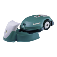
Related product manuals