Interface Box of the aviation plug version LiDAR is 3 meters, for other cable lengths, please contact
RoboSense technical support).
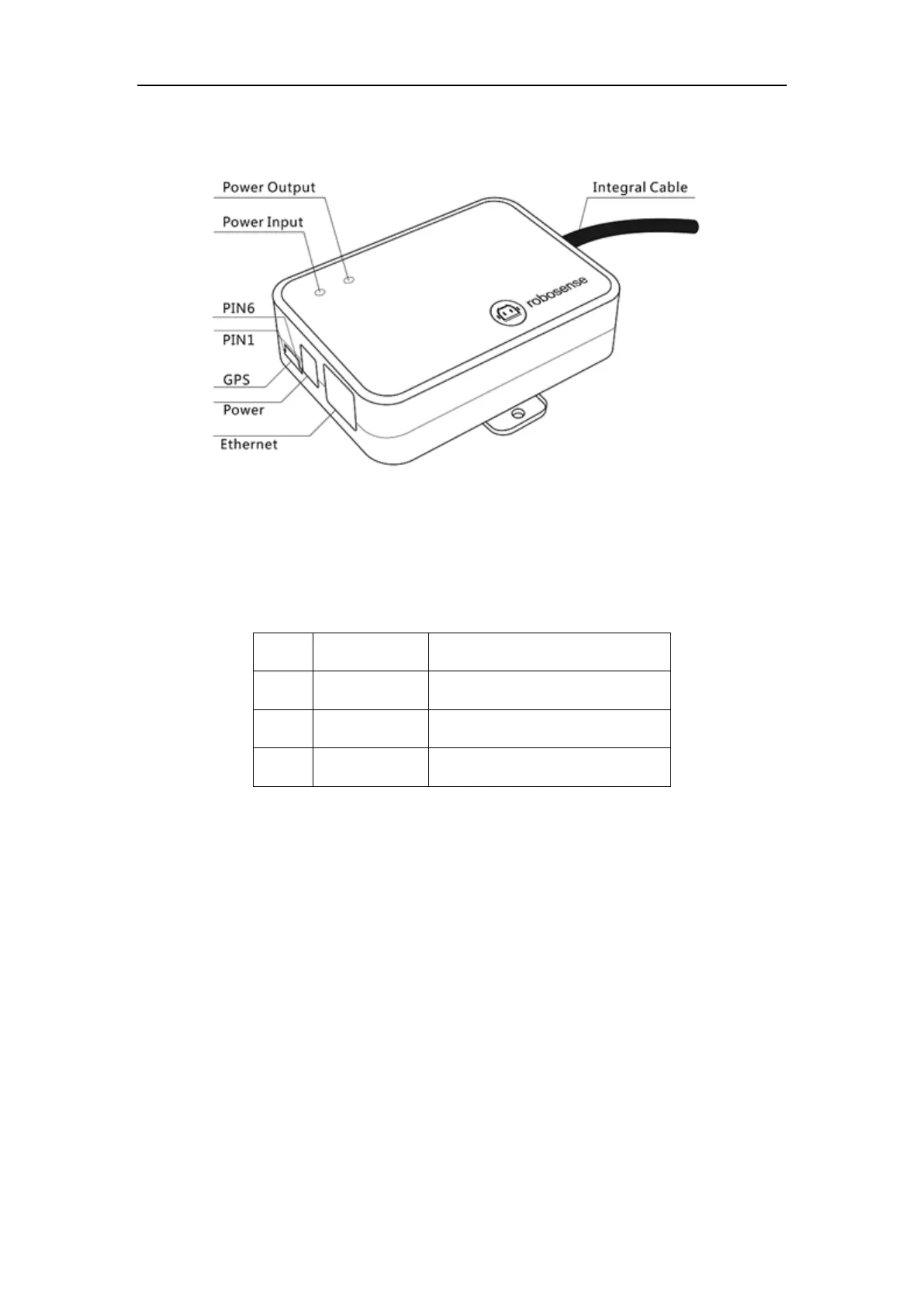
Figure 3 Definition of Interface Box Ports
Specifications of Interface Box ports:
Table 1 Interface Box Port Specification
3.3.1 Power
The power supply interface on the Interface Box is a standard DC 5.5-2.1 connector.
There are 2 LEDs in the Interface Box: when the power input is normal, the red LED lights up; when
the power output is normal, the green LED lights up. If the power indicator is dimmed, the Interface
BOX may not work properly. Please check whether the power input is normal. If the power input is
normal, the Interface BOX may be damaged. Please contact RoboSense technical support & sales
for help.
3.3.2 RJ45 Ethernet Port
The network interface on the Interface Box follows the EIA/TIA568 standard.
3.3.3 GPS Time Synchronization
RS-Helios-16P uses GPS for Time Synchronization: the GPS REC receives GPS UART standard input; GPS PULSE
 Loading...