Setting the control mode
The LED selection of control modes and corresponding
pump curves takes place in clockwise succession.
•Presstheoperatingbuttonbriey(approx.1second).
- LEDs display the set control mode and pump curve.
The following shows the various possible settings, beginning with
the factory setting:
Appendices
Wilo Para HU 25/6-43/SCU Manual
Venting
Fill and vent the system correctly.
If the pump does not vent automatically:
• Activate the pump venting function via the operating button:
press and hold for 3 seconds, then release.
- The pump venting function is initiated and lasts 10 minutes.
-ThetopandbottomLEDrowsashinturnat1secondintervals.
• To cancel, press and hold the operating button for 3 seconds.
NOTICE: After venting, the LED display shows the
previously set values of the pump.
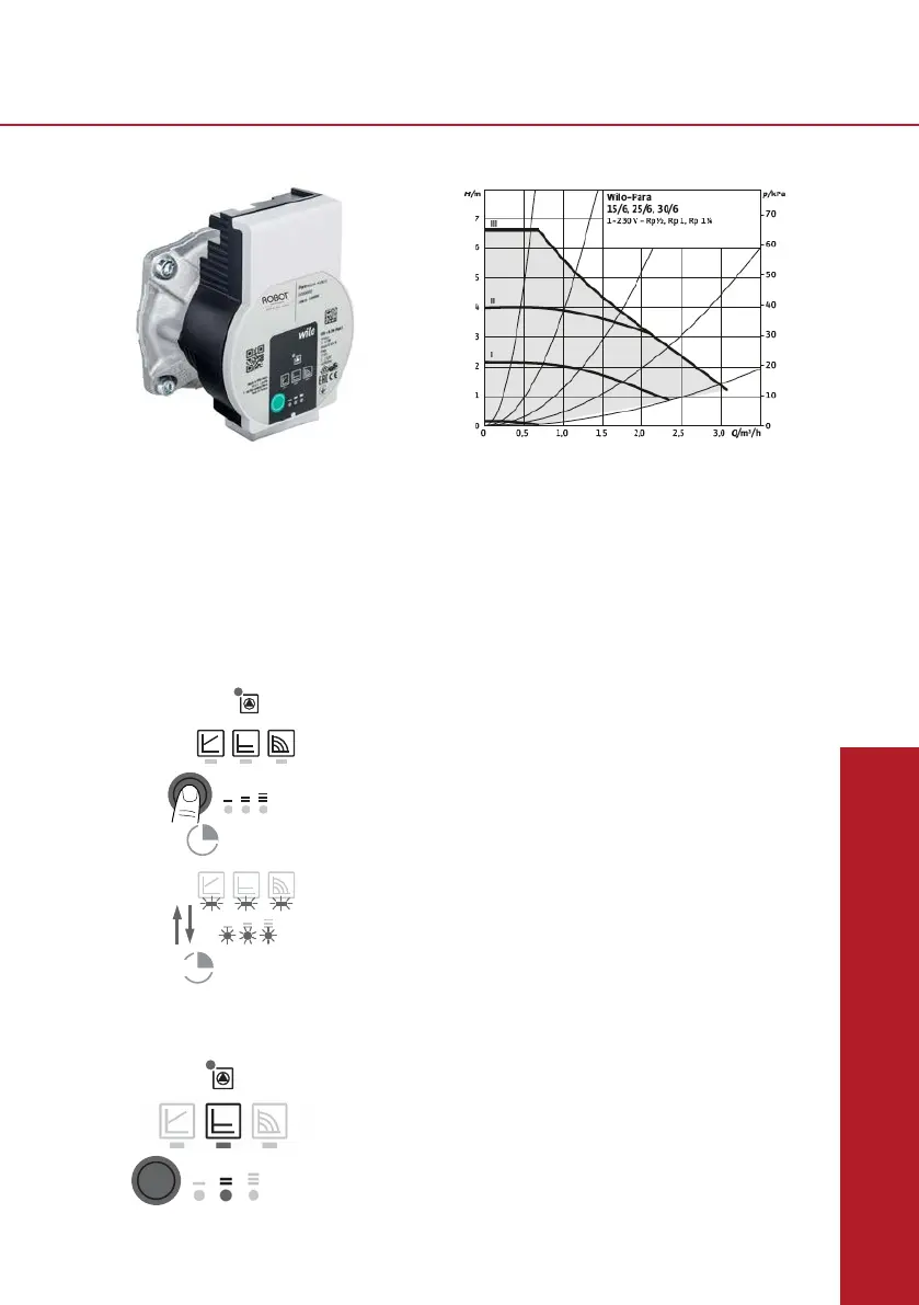
ConstantdifferentialpressureΔp-c(I,II,III)
Recommendedforunderoorheatingorforlarge-sizedpipes,applicationswithoutavariable
pipenetworkcurve(e.g.storagechargepumps)orsingle-pipeheatingsystemswithradiators.
Thecontrolkeepsthesetdeliveryheadconstantirrespectiveofthepumpedvolumeow.There
arethreepre-denedpumpcurves(I,II,III)tochoosefrom.
SettingI=2metre(20kPa);
SettingII=3metre(30kPa)advisedsettingforgrouplengthsupto90metreeach;
SettingIII=4,5metre(45kPa)advisedsettingforgrouplengthsupto120metreeach.
Hydraulic operational area
Heating
03/18
Datasheet Wilo-Para **-***/6-43/SCU
0
0,5
1
1,5
2
2,5
3
3,5
4
4,5
5
0 1 2 3 4
H (mCE)
Q (m3/h)
Δp-c (constant)
III
II
Standard factory setting*
*If needed, this factory setting is customisable
on request.
e.g. Δp-c / Speed II
Appendices
Inbouw- en bedieningsvoorschriften Wilo-Para 21
nl
7 Inbedrijfname
Inbedrijfname uitsluitend door een gekwalificeerde
specialist laten uitvoeren.
7.1 Ontluchten
• Installatie op een correcte manier vullen en ont-
luchten.
Indien de pomp niet vanzelf ontlucht:
• Ontluchtingsfunctie via de bedieningstoets
activeren, 3 seconden indrukken, vervolgens loslaten.
De ontluchtingsfunctie start en houdt
ongeveer 10 minuten aan.
De bovenste en onderste LED-rijen knipperen afwis-
selend met een afstand van 1 seconde.
• Om te annuleren de bedieningstoets 3 seconden
indrukken.
VOORZICHTIG!
De aansluiting van netspanning (230 V AC) op de com
-
municatiepinnen (iPWM/LIN) vernietigd het product.
• Bij de PWM ingang bedraagt de maximale span-
ningshoogte 24 V pulsingangsspanning.
sec3
min10
LET OP
Na het ontluchten toont de LED-weergave
de eerder ingestelde waarden van de pomp.
22 Wilo SE 07/2018
nl
7.2 Regelingstype instellen
Regelingstype
selecteren
De LED-selectie van de regelingstypes en de bijbeho-
rende karakteristieken vindt rechtsom plaats.
• Bedieningstoets kort (ca. 1 seconde) indrukken.
LED's geven het ingestelde regelingstype en de
karakteristiek aan.
De weergave van de mogelijke instellingen hierna
(bijvoorbeeld: Constant-toerental / karakteristiek III):
Led-weergave Regelingstype Karakteristiek
1. Constant toerental
II
2. Constant toerental
I
3. Verschildruk variabel
Δp-v
III
4. Verschildruk variabel
Δp-v
II
5. Verschildruk variabel
Δp-v
I
6. Verschildruk constant
Δp-c
III
7. Verschildruk constant
Δp-c
II
 Loading...