Pag. 49
4. IMPIANTO ELECTTRICO
IN FASE DI COLLEGAMENTO DELL'APPARECCHIO ALLA RETE ELETTRICA OSSERVARE
TUTTE LE NORMATIVE LOCALI, COMPRESE QUELLE RIFERITE A DISPOSIZIONI
NAZIONALI O EUROPEE.
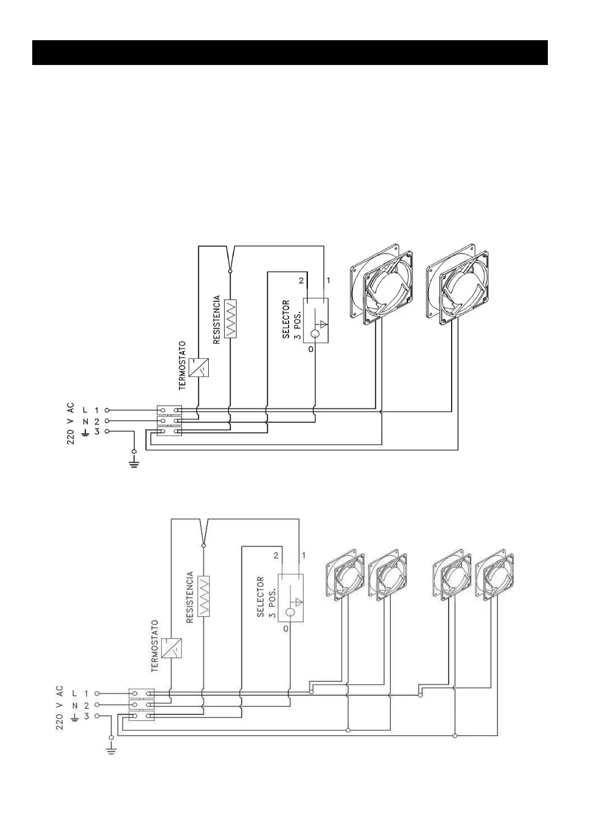
4.1. Componenti. L'apparecchio è dotato di due turbine elicoidali per i modelli RCr 50 V, RCr 50 V –
GARFFITI, RCr 65, RCr 70, RCr 70 GRAFFITI, RCr 70 A, RCr 70 A-GRAFFITI e RCr 70 CONICO e di
quattro turbine per i modelli RCr 80, RCr 80 GRAFFITI, RCr 100 e RCr 100 GRAFFITI, termostato per
l'avvio delle turbine, resistenza, interruttore di controllo velocità turbine, cablaggio interno e tubo in
silicone per l'uscita esterna.
4.2. Schema elettrico per funzionamento con 2 turbine
4.2. Schema elettrico per funzionamento con 4 turbine