Do you have a question about the Rockford Fosgate Power BD500.1 and is the answer not in the manual?
| Brand | Rockford Fosgate |
|---|---|
| Model | Power BD500.1 |
| Category | Amplifier |
| Language | English |
Lists all accessories included with the amplifier for installation and use.
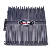
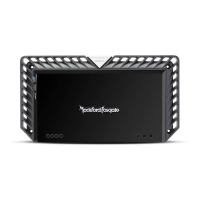
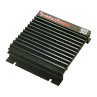
The cast aluminum heatsink dissipates heat generated by circuitry, improving cooling over extrusion designs.
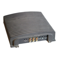
Heavy duty, gold-plated terminal blocks accept wire sizes 8 AWG to 18 AWG and are immune to corrosion.
Heavy duty, gold-plated terminal blocks accept wire sizes 4 AWG to 12 AWG and are immune to corrosion.
Spade terminal for remotely turn-on/turn-off the amplifier with +12V DC applied.
Industry standard RCA jacks for signal level input, gold-plated to resist signal degradation caused by corrosion.
Convenient source for daisy-chaining additional amplifiers without extra RCA cables.
Input gain control preset to match source units, adjustable to match output levels.
Corrects acoustical deficiencies, reproduces full range sound. Narrow band adjustment at 45Hz.
Built-in 24dB/octave Butterworth filter, variable from 50Hz to 250Hz. Can be set to Low-Pass.
Red LED illuminates when unit is in protection. Requires momentary AP removal.
6 pin mini DIN connector for bridging two amplifiers in bridge mode for synchronization.
High pass filter to prevent frequencies below audio range from reaching amplifier core.
Carefully read and understand instructions before attempting installation.
For safety, disconnect the negative battery lead prior to beginning installation.
Suggest running all wires prior to mounting amplifier for easier assembly.
Route RCA cables close together and away from high current wires to prevent noise.
Use high quality connectors for reliable installation and to minimize signal/power loss.
Be careful not to cut or drill into gas tanks, fuel lines, or wiring when working on vehicle.
Never run wires underneath the vehicle; running inside provides best protection.
Avoid sharp edges for wires; use grommets to protect wires routed through metal.
Always protect battery/electrical system with proper fusing on +12V power wire.
Scrape paint from chassis metal for good ground; connections should be short and to main body/chassis.
Mounting amplifier vertically with fins up/down provides best cooling.
Ensure sufficient airflow for cooling. If under seat, maintain at least 1" air gap around heatsink.
Never mount in engine compartment; voids warranty and is not recommended.
Plan wire routing, keeping RCAs separate from power cables and electric motors to prevent noise.
Strip 5/8" insulation from power cable end, strip at 45° angle, insert into B+ terminal.
Strip 3/8" from battery end of power cable, crimp ring terminal, connect to battery positive terminal.
Prepare ground cable, clean chassis metal, strip wire, attach ring connector, fasten to chassis.
Prepare REM wire, strip 1/4", crimp spade connector, connect to REM terminal and switched 12V source.
Mount amplifier securely with screws. Avoid cardboard/plastic panels to prevent pull-out.
Connect source signal by plugging RCA cables into input jack(s) at the amplifier.
Strip speaker wires 5/8", insert into terminal, tighten set screw. Maintain polarity, do not chassis ground leads.
Perform final check of all connections for accuracy, frayed wires, and loose connections.
Use BDSYNC cable for bridging; join speaker grounds with 8 gauge wire, max 15".
Verify power light, in-line fuse, and ground connection. Check voltage at battery and remote turn-on cable.
Connect test speaker to each output channel. Verify RCA/high-level input connections.
Disconnect input signal and test. Use delay module or relay for REM lead if noise persists.
Route signal wires away from power wires. Bypass components. Reground wires, add chassis ground, or test vehicle electrical system.