MicroLogix 1400 Programmable Controllers 23
Publication 1766-IN001D-EN-P - June 2015
Grounding the Controller
In solid-state control systems, grounding and wire routing helps limit the effects of noise due
to electromagnetic interference (EMI). Run the ground connection from the ground screw of
the controller to the ground bus prior to connecting any devices. Use AWG #14 wire. For
AC-powered controllers, this connection must be made for safety purposes.
You must also provide an acceptable grounding path for each device in your application. For
more information on proper grounding guidelines, refer to the Industrial Automation Wiring
and Grounding Guidelines, publication 1770-4.1.
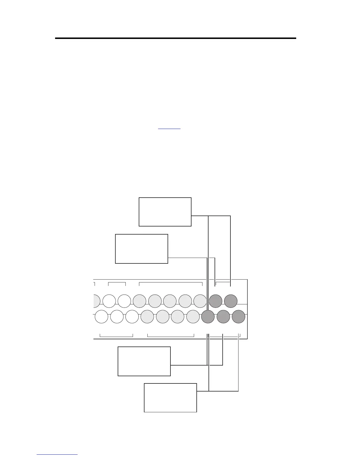
Wiring Your Analog Channels
Analog input circuits can monitor voltage signals and convert them to serial digital data as
shown in the following illustration.
Analog Input
IV0(+) IV2(+)
IV1(+) IV3(+)
/7
COM 2
I/8 I/10
I/9 I/11
COM 3
I/13 I/15 I/17 I/19
I/12 I/14 I/16 I/18
COM
ANA
Input Terminal Block
Sensor 1
(V) Voltage
Sensor 2
(V) Voltage
44529
Sensor 0
(V) Voltage
Sensor 3
(V) Voltage
 Loading...


