Do you have a question about the Rockwell Automation 1763-L16AWA and is the answer not in the manual?
| Brand | Rockwell Automation |
|---|---|
| Model | 1763-L16AWA |
| Category | Controller |
| Language | English |
Defines WARNING, IMPORTANT, ATTENTION, SHOCK HAZARD, and BURN HAZARD icons and meanings.
Lists available manuals, online resources, and how to obtain them.
Highlights key precautions for controller installation and handling ESD sensitive parts.
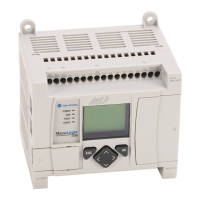
Identifies and describes the main components and ports of the MicroLogix 1100 controller.
Details specifications for different MicroLogix 1100 catalog numbers.
Details explosion hazard warnings and installation requirements for hazardous environments.
Lists approved communication cables for use in Class I, Division 2 hazardous environments.
Provides general guidelines for controller placement to minimize electrical interference and environmental exposure.
Provides physical dimensions for mounting the controller and its variants.
Advises on vertical mounting limitations and care during drilling to avoid damage.
Specifies required spacing for adequate ventilation and controller placement.
Details the procedure and dimensions for mounting the controller onto a DIN rail.
Provides step-by-step instructions for mounting the controller using mounting screws.
Explains how the LCD display indicates the battery status and its implications.
Details the procedure for connecting 1762 I/O expansion modules to the controller.
Illustrates terminal block layouts for different MicroLogix 1100 models.
Specifies wire types, sizes, and torque for terminal connections.
Provides guidance on terminal block wiring and stripping procedures.
Explains the need for surge suppression for inductive loads to protect controller outputs.
Details the importance of grounding for noise reduction and safety, and general grounding advice.
Describes how analog input circuits monitor voltage signals and convert them to digital data.
Provides steps to reduce the effects of environmental noise on analog signals.
Details how to properly ground shielded communication cables for analog channels.
Lists the physical dimensions and shipping weight of the controllers.
Details power supply voltage requirements and power consumption for each model.
Covers certifications and immunity standards (ESD, RF, Transient, Conducted).
Details on-state/off-state voltage ranges and on-state current for digital inputs.
Covers output specifications (relay/FET) for hazardous location applications.
Details output specifications (relay/FET) for non-hazardous (ordinary) locations.
Provides detailed relay contact ratings for various voltage and current conditions.
Includes a relay life chart and specifications for BBB FET outputs.
Details maximum output current, surge current, and repetition rates for FET outputs.
Specifies working voltage limits and dielectric test results for the 1763-L16AWA controller.
Specifies working voltage limits and dielectric test results for the 1763-L16DWD controller.
Provides contact information for technical assistance during the first 24 hours of installation.
Outlines the process for returning products that are not functioning correctly.


 Loading...