Do you have a question about the Rockwell Automation 1766-L32BXBA and is the answer not in the manual?
| Product Type | Programmable Logic Controller (PLC) |
|---|---|
| Input Voltage | 24V DC |
| Memory | 32 KB |
| Output Voltage | 24V DC |
| Analog Inputs | 0 |
| Analog Outputs | 0 |
| Power Supply | 24V DC |
| Operating Temperature | 0°C to 60°C |
Details the scope and objectives of the user manual for MicroLogix 1400 controllers.
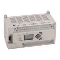
Describes the physical components and capabilities of the MicroLogix 1400 controller.
Explains the software and process for programming the MicroLogix 1400 controller.
Provides guidance on environmental and enclosure requirements for controller installation.
Details critical safety precautions for handling and installing the controller and related equipment.
Explains important factors related to power supply and distribution for the controller.
Describes the function and wiring of the Master Control Relay for emergency shutdown.
Details the procedures for mounting the controller using DIN rail or panel mount methods.
Details the procedures for mounting the 1762 Expansion I/O modules.
Provides general guidelines and recommendations for wiring the controller and system.
Details the proper grounding procedures to limit EMI effects and for safety.
Provides guidance on minimizing electrical noise in controller I/O wiring.
Lists the communication protocols supported by the controller's communication channels.
Details the default communication settings for Channel 0 of the MicroLogix 1400.
Describes methods for connecting the controller to a PC using the DF1 protocol.
Provides examples and considerations for connecting to an RS-485 network.
Explains how to connect the MicroLogix 1400 controller directly to an Ethernet network.
Describes how to view the real-time status of inputs and outputs on the controller's LCD screen.
Details how to view and configure the controller's Ethernet network settings.
Details the operation of the built-in real-time clock at power-up and in run/test modes.
Provides essential cautions and requirements before starting an online editing session.
Explains the controller's ability to automatically recover from certain faults.
Describes the conditions and states for enabling the auto reset functionality.
Details the electrical specifications for the controller's input modules.
Provides general specifications for the digital I/O modules used with the controller.
Provides detailed electrical specifications for various input modules.
Provides detailed electrical specifications for various output modules.
Explains the meaning of the LED and LCD status indicators on the controller.
Details how controller status indicators reflect error conditions.
Provides a flowchart to diagnose and recover from controller errors.
Distinguishes between recoverable and non-recoverable module and channel errors.
Lists prerequisites for upgrading the controller's operating system firmware.
Details necessary steps for the controller before initiating a firmware update.
Provides step-by-step instructions for performing the firmware upgrade using ControlFLASH.
Describes the RS-232 standard and its characteristics for serial communication.
Details the RS-485 interface and its use in multi-drop network configurations.
Details the DH-485 protocol and its features for communication between devices.
Details how to configure serial and Ethernet channels for DNP3 protocol.
Guides on downloading and uploading user programs using DNP3 communication.
Introduces Ethernet as a LAN for device communication and physical media options.
Details the three methods for configuring the controller's Ethernet channel.
Explains how to calculate the electrical load on the controller's power supply.
Provides a table to determine the heat dissipation of system components for enclosure installation.


