FLEX I/O Digital DC Output Modules 11
Publication 1794-IN094D-EN-P - July 2018
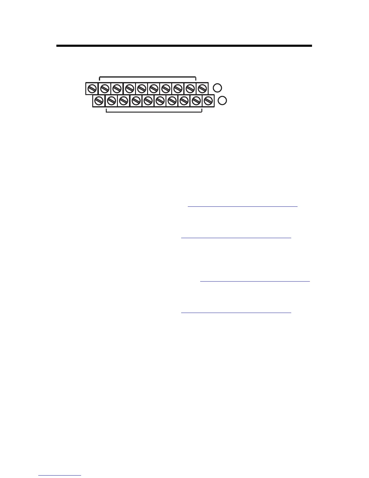
1794-TBN Terminal Base Wiring for 1794-OB8EP
Connect Wiring for the 1794-OB32P
1. Connect individual output wiring (OUT0…OUT15) to numbered terminals on
the 0…15 row (A) as indicated in the Wiring Connections for 1794-OB32P
table.
2. Connect the associated power to the +V1 terminal (35, 37, 39, or 41) on the
34…51 row (C) as indicated in the Wiring Connections for 1794-OB32P
table.
3. Connect the associated output common (-V1)for OUT0 to OUT15 to COM1
(terminal 36, 38, 40, or 42) on the 34…51 row (C).
4. Connect individual output wiring (OUT16…OUT31) to numbered terminals
on the 16…33 row (B) as indicated in the Wiring Connections for 1794-OB32P
table.
5. Connect the associated power to the +V2 terminal (43, 45, 47, or 49) on the
34…51 row (C) as indicated in the Wiring Connections for 1794-OB32P
table.
6. Connect the associated output common (-V2) for OUT16…OUT31 to COM2
(terminals 44, 46, 48, or 50) on the 34…51 row (C).
7. If continuing power to the next terminal base, connect a jumper from terminal
35, 37, 39, or 41 (+V1) and 43, 45, 37, or 49 (+V2) on this base unit to the power
terminal on the next base unit.
8. If continuing output common return to the next base unit, connect a jumper
from terminal 36, 38, 40 or 42 (COM1) and 44, 46, 48 or 50 (COM2) on this
base unit to common on the next base unit. Refer to the installation instructions
for the next type of terminal base unit.
16
0
1
2
3
4
5
6
7
8
9
10
11
12
13
14
15
51
33
34
+V
COM
+V
COM
B
C
Even Numbered I/O Terminals 0 thru 14
Odd Numbered I/O Terminals 1 thru 15
Connect -V (Supply Common) to terminal B-16
Connect +V (Supply +Voltage) to terminal C-34
(Use B-33 and C-51 for daisy-chaining to next terminal base unit.)
Total current draw through the terminal base is limited to 10A. Separate power
connections to each terminal base may be necessary.
 Loading...


