18 Rockwell Automation Publication 440R-UM013F-EN-P - July 2021
Chapter 3 Power, Ground, and Wire
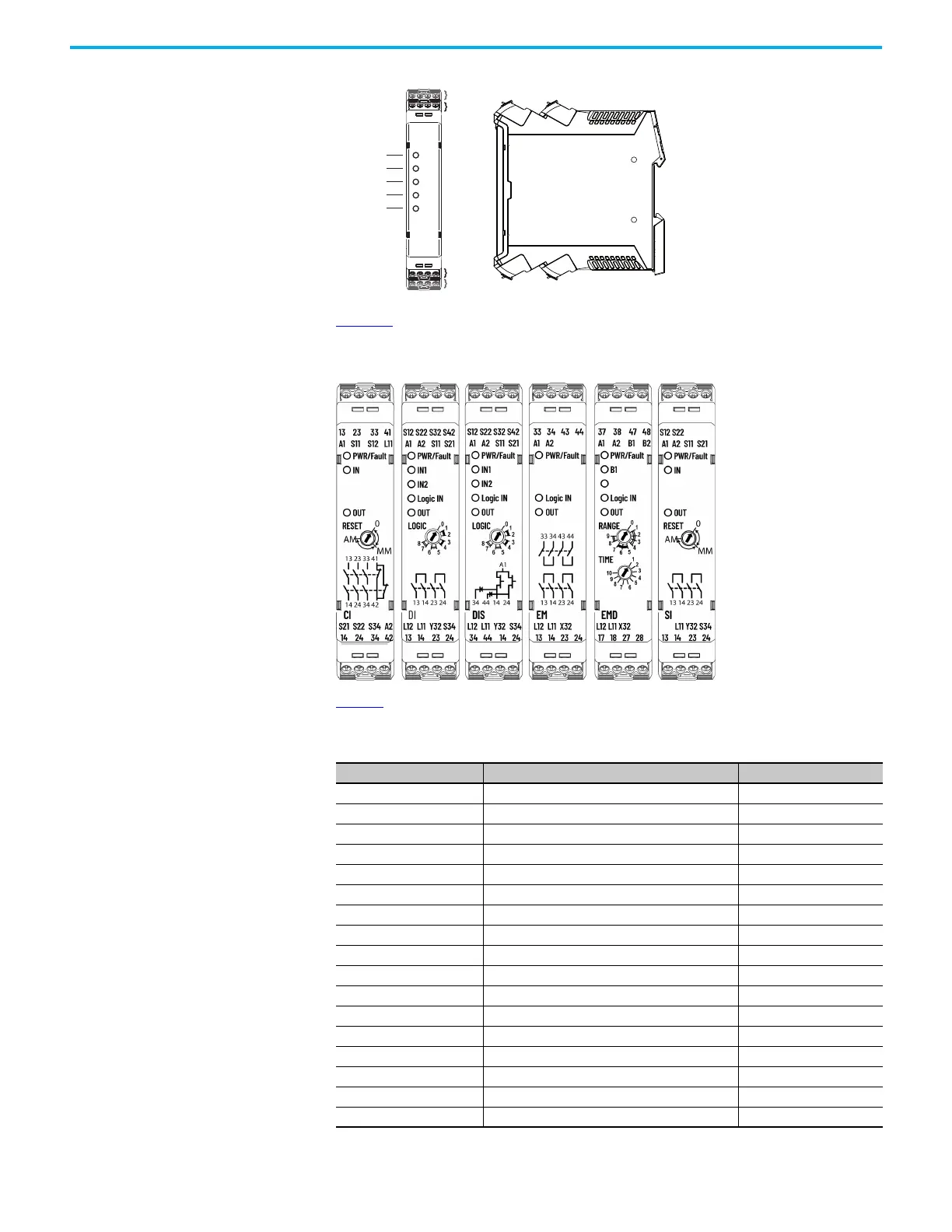
Figure 5 - Terminal Identification
Figure 6 shows the markings on the front face of each safety relay, including
the terminal and status indicator identifications.
Figure 6 - Relay Face Markings
Table 1 lists the terminal functions. Many of the terminals perform common
functions on multiple relays.
Table 1 - Terminal Assignments and Functions
Terminal Function Applies To
A1 +24V Supply (+10%, -15%) All
A2 24V Common All
S11 Pulse Test Output for Channel 1 CI, DI, DIS, and SI
S21 Pulse Test Output for Channel 2 CI, DI, DIS, and SI
S12 Safety Input for IN1 Channel 1 CI, DI, DIS, and SI
S22 Safety Input for IN1 Channel 2 CI, DI, DIS, and SI
S32 Safety Input for IN2 Channel 1 DI and DIS
S34 Reset Input CI, DI, DIS, and SI
S42 Safety Input for IN2 Channel 2 DI and DIS
Y32 Auxiliary Non-safety Output CI, DI, DIS, and SI
X32 Auxiliary Non-safety Output EM and EMD
B1 Jog Input EMD
B2 Retrigger Input EMD
L11 Single Wire Safety Output All
L12 Single Wire Safety Input DI, DIS, EM, and EMD
13/14, 23/24 Safety Outputs - electromechanical relay CI, DI, EM, and SI
33/34, 43/44 Safety Outputs - electromechanical relay EM
S12 S22 AP S54
A1 A2 P12 P22
X2
X1
X1
X2
X3
X4
X3 X4
PWR/Fault
IN1
51/L61
Logic IN
X14/X24 L11
L12 L11 Y32 S44
X14 X24 51 L61
 Loading...


