6 ControlLogix Multi-Vendor Interface Module
Publication 1756-IN001A-US-P - May 2000
Prepare the Chassis for Module Installation
Before you install the MVI module, you must install and connect a
ControlLogix chassis (1756-A4, 1756-A7, 1756-A10, or 1756-A13) and
power supply (1756-PA72 or 1756-PB72). To install these products,
refer to publications 1756-5.1 and 1756-5.2.
Identify Module Features
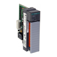
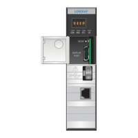
Use the figure below to identify the external features of the module.
chassis
power
supply
1756-A4
Chassis
Power
Supply
Backplane
Connector
Channel and
Module Status
Indicators
Door
Port 1
Port 2
Port 3
Wiring
Label
FRONT VIEW
Flash
Card
PRT2PRT3
SETUP
SIDE VIEW
NOTE: Jumpers are located on the back of
circuit board when viewed from this side.
PRT1
PRT2
PRT3
Compact
(Optional)

 Loading...

