Publication 1756-RM004B-EN-P - October 2000
1756-MVI Module Overview 1-3
LED Indicators
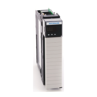
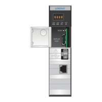
The 1756-MVI module has seven LED indicators at the top of its front
panel. Five of these indicators display the module’s status and port
activity. The other two, LEDs U1 and U2, are controlled by the user
application and may be used for any purpose.
Figure 1.2 LED Indicators
LED Description Status Meaning
P1, P2, P3 Port Activity Off No serial activity detected on corresponding port.
Green Serial activity detected on corresponding port.
U1, U2 User Defined - Application dependent.
BATT Battery Off Battery voltage normal.
Red Battery voltage low. Service required.
OK
(1)
(1)
Defaults shown. The OK LED can also signify Status determined by the user-programmable
“SetModuleStatus” command. Note that neither the SetModuleStatus command nor the
BIOS/hardware has priority on the LED, so each can overwrite the other.
Module Status Off Power is OFF or module is not installed.
Green Power is ON. Normal Operation.
Red Power up non-recoverable fault.
Flashing
Green/Red
NVS update in progress.
Not configured.
(2)
Not connected.
(2)
Recoverable major fault.
(2)
(2)
These are “typical” for ControlLogix modules. Because the MVI module is user-programmable,
this has to be implemented by the user.

 Loading...

