2 Rockwell Automation Publication 442G-IN004C-EN-P - January 2020
Multifunctional Access Box with CIP Safety over EtherNet/IP
Power Supply Requirements
Electrical Connection
Connections on Bus Module
This section describes the power connectors, EtherNet/IP connectors,
and recommended cables.
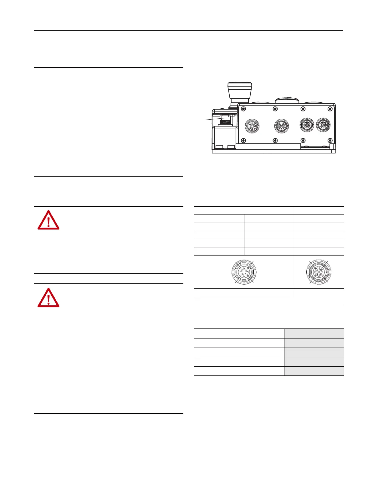
Figure 1 - Connections on Bus Module
Power Connections
The bus module includes the EtherNet/IP connections (X3 and X4,
M12 D-coded) and the power supply connections (X1 and X2).
IMPORTANT • If the device does not appear to function when the
operating voltage is applied (for example, Pwr status
indicator does not illuminate), the safety switch must be
returned to the manufacturer.
• A Class 2 PELV power supply must be used. Alternative
solutions must comply with the following requirements.
- Electrically isolated power supply unit with a
maximum open-circuit voltage of 30V DC and a
limited current of 8 A maximum.
- Electrically isolated power supply unit in
combination with the fuse as per UL 248. This fuse
should be designed for a maximum of 3.3 A and
should be integrated into the 30V DC voltage
section.
• The functional earth ground must be connected. An M6
threaded bore is available on the mounting plate of the
lock/bus module for this purpose.
WARNING: Connect and disconnect wiring cables:
• If you connect or disconnect wiring or cables while the field-
side power is on, an electric arc can occur. This arc could cause
an explosion in hazardous location installations. Be sure that
power is removed or the area is nonhazardous before
proceeding.
• If you connect or disconnect the communication cables while
power is applied to this module or any device on the network,
an electric arc can occur. This arc could cause an explosion in
hazardous location installations.
ATTENTION: Wiring Guidelines
• All electrical connections must be isolated from the main
supply by a safety transformer (according to EN IEC 61558-2-6)
with limited output voltage if there is a fault or by other
equivalent isolation measures.
• Power devices, which are a powerful source of interference,
must be installed in a separate location away from the input
and output circuits for signal processing. The cable routing for
safety circuits must be as far away as possible from the cables
of the power circuits.
• To avoid EMC interference, the physical environment and
operating conditions at the installation site of the device must
comply with the requirements according to the standard
DIN EN 60204-1:2006, section 4.4.2/EMC.
• The mounting of conduits directly on the access box is not
allowed. Cables are only allowed to be connected via suitable
cable glands. Use a UL Listed (QCRV) cable gland suitable for
the related cable diameter (22…17 AWG).
• The functional earth must be connected. An M6 threaded bore
is available on the mounting plate for this purpose.
Table 1 - Pinout for Power Connectors (M12 A-coded models)
Pin Description
X1.1 X2.1 24V DC
X1.2 X2.2 Pass through
X1.3 X2.3 0V DC (GND)
X1.4 X2.4 Pass through
X1.5 X2.5 Functional earth
X1 X2
Power supply connector assignment. Connectors X1 and X2, M12 A-coded.
Table 2 - Recommended Micro Power Cables
Description Cat. No.
(1)
(1) Replace -2 (2 m [6.6 ft]) with -5 (5 m [16.4 ft]) or -10 (10 m [32.8 ft]) for additional standard cable lengths.
Micro straight female to flying leads cordset 889D-F4AC-2
Micro straight male to flying leads cordset
889D-M4AC-2
Micro right-angle female to flying leads cordset
889D-R4AC-2
Micro right-angle male to flying leads cordset
889D-E4AC-2
X1
X4X3
X2
IN 24V DC
LINK 1 LINK 2
OUT 24V DC
X5
1
2
43
1 2
43
 Loading...