Rockwell Automation Publication 442G-IN004C-EN-P - January 2020 5
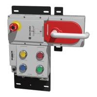
Multifunctional Access Box with CIP Safety over EtherNet/IP
Mechanical Function Test
Electrical Function Test
Perform following steps.
1. Switch on operating voltage.
2. Close all safety guards and insert the bolt actuator into the
locking module. For Power to Lock versions, activate guard
locking.
• The machine must not start automatically.
• It must not be possible to open the safety guard.
• The State status indicator and the Lock status indicator are
illuminated continuously.
3. Use the control system to start the machine.
• It must not be possible to open the guard door as long as
the machine is running.
4. To stop the machine and unlock the door, use the control
system.
• The safety guard must remain locked until there is no
longer any risk of injury.
• It must not be possible to start the machine as long as the
guard locking is deactivated.
• It must be possible to open the safety guard.
Repeat steps 2
…4 for each safety guard.
Connect the Multifunctional Access Box to the
EtherNet/IP Network
The MAB has two Ethernet ports that support 10/100/1000 Mbps.
Connect a CAT 5e or CAT 6 Ethernet cable with M12 connectors to
the Ethernet ports (X3 and X4) on the underside of the Bus module.
For information on how to select the proper cable, see publication
ENET-WP007
.
You must also configure an Ethernet driver for your workstation by
using RSLinx® Classic Software. See Add a Driver in the RSLinx
Classic software Help.
Inspection and Service
Periodically check the correct operation of the switching function.
Also check for signs of abuse or tampering. Inspect the switch casing
for damage. Check the safe function of the device particularly after any
of the following:
• Set-up work
• The installation or replacement of any hardware
• An extended period without any use
•A fault condition
IMPORTANT
It must be possible to insert the bolt actuator in the locking
module. To check, close the safety guard several times and
actuate the guard door handle.
If available, check the function of the escape release. It must
be possible to operate the escape release from the inside
without excessive force (approximately 40N (8.99 lbf).
ATTENTION: The escape release must only be accessible from
inside the safeguarded area. Access to the escape release from
outside the safeguarded area must not be allowed.
WARNING: Safety components perform a personal protection
function. They must not be bypassed, removed, or otherwise
rendered ineffective. Only the intended handle assembly that is
properly mounted to the safety guard is allowed to trigger the
switching operation.
ATTENTION: If there is a malfunction or damage to the product,
attempts at repair must not be made. The unit must be replaced or
alternative safeguarding must be implemented before machine
operation is allowed.
 Loading...